Long and short laser pulse synchronization device

A laser pulse and synchronization device technology, which is applied in the direction of lasers, laser components, phonon exciters, etc., can solve the problems of limiting synchronization accuracy, unsatisfactory, and application field limitations, so as to avoid the limitation of repetition frequency, low cost, and The effect of high synchronization accuracy

Inactive Publication Date: 2016-08-31
SHANGHAI INST OF OPTICS & FINE MECHANICS CHINESE ACAD OF SCI
View PDF5 Cites 2 Cited by
  • Summary
  • Abstract
  • Description
  • Claims
  • Application Information

AI Technical Summary

Problems solved by technology

This kind of time jitter limits the stability of the relative time delay between multiple laser pulse signals to the order of nanoseconds, which cannot meet higher precision triggering
The technical scheme of long and short pulse time synchronization based on optical fiber pulse stacking to achieve arbitrary long pulse shaping (see the prior art [2] invention patent: synchronization device for ultrashort pulse and arbitrarily shaped long pulse) can obtain high-precision long and short pulse synchronization, but its The shaping signal of arbitrary shaped pulses comes from the time stacking of ultrashort chirped pulses, and its application field is limited to chirped pulses, because only the stacking of chirped pulses can avoid the interference effect introduced by the pulse superposition on the shaped waveform. stability impact
Obtain a high-precision synchronous trigger signal based on optical fiber pulse stacking, generate a high-speed square wave through a trigger signal generator, and then obtain arbitrarily shaped electrical signals through an aperture-coupled stripline. It can be applied to the synchronization of chirped or non-chirped short pulses with arbitrary shaped long pulses, but because a high-speed signal generator is required in the scheme, its repetition frequency can only be within 10KHz, and the triggering process of the signal generator will introduce additional time jitter, which limits the improvement of its synchronization accuracy

Method used


Image

  • Long and short laser pulse synchronization device
  • Long and short laser pulse synchronization device

Examples


Embodiment Construction

[0022] The present invention will be further described below in conjunction with the embodiments and accompanying drawings, but the protection scope of the present invention should not be limited thereby.

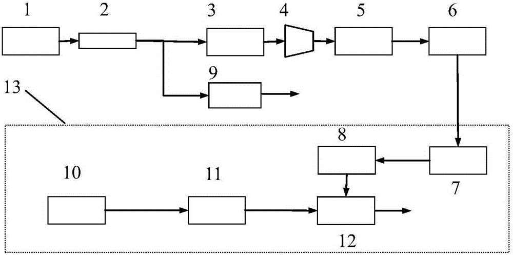
[0023] Please see first figure 1 , figure 1 It is a schematic circuit diagram of the long and short laser pulse synchronization device of the present invention. The long-short laser pulse synchronization device of the present invention consists of a short-pulse laser system 1, a 1×2 beam splitter 2, an optical pulse stacker 3, a high-speed photoelectric tube 4, a fast comparator 5, a broadband high-speed electric amplifier I 6, and aperture-coupled microstrip line shaping Board 7, broadband high-speed electric amplifier II8, adjustable delayer I9, long pulse laser 10, adjustable delayer II11, and amplitude modulator 12. The output of the short-pulse laser system 1 is an optical pulse signal with a pulse width of 140 ps and a repetition frequency of 1 Hz obtained by stretc...


PUM


Abstract

A long and short laser pulse synchronization device is applicable to high precision time synchronization between short laser pulses and arbitrarily-shaped long laser pulses, and a stable relative time relation between multiple paths of laser pulse signals is realized. Beam splitting is carried out on light outputted by a short laser pulse system by a 1*2 beam splitter, a beam of light obtained through beam splitting sequentially passes through an optical pulse accumulation device, a high-speed photoelectric tube, a fast comparator and a first wideband high speed electric amplifier, and after outputted square wave electrical signals are subjected to shaping of an aperture coupled microstrip line shaping plate and amplification of a second wideband high speed electric amplifier, the signals are inputted to a radio frequency input end of an amplitude modulator. In addition, output light of a long pulse laser enters the amplitude modulator via a second adjustable delay device, and the amplitude modulator outputs shaped light pulses. The relative time jitter between light pulses outputted by the shaped light pulses and the short pulse laser system is 3.5 ps (mean square root, five hours), the repetition frequency can achieve MHz order of magnitude, and the device of the invention has the advantages of compact structure, reliable work, low cost and easy extension.

Description

technical field [0001] The invention relates to a multi-channel laser pulse synchronization device, specifically a long and short laser pulse synchronization device, which is mainly suitable for high-precision time synchronization between short laser pulses and arbitrarily shaped long laser pulses, and realizes stable relative time between laser pulse signals relation. Its advantages are high relative time stability between pulses, compact structure, stable operation, optical fiber, and long-term relative time jitter between laser pulses is 3.5ps (root mean square, 5 hours). Background technique [0002] In the ultra-short and ultra-intense laser system, accurate and stable multi-channel laser pulse time control is an important technology, which has an important impact on the reliability and accuracy of the entire system. For example, in the long-short pulse joint driving experiment, the relative time between the probe light pulse and the main laser pulse and its relative t...

Claims


Application Information

Patent Timeline
Patent Type & Authority Applications(China)
IPC IPC(8): H01S3/094
CPCH01S3/094026H01S3/094053H01S3/094076
Inventor 汪小超李玉荣乔治井媛媛陈杰张生佳范薇
Owner SHANGHAI INST OF OPTICS & FINE MECHANICS CHINESE ACAD OF SCI
Why Eureka
Try Eureka