Planar transformer

A planar transformer, together technology, applied in the direction of transformer/inductor core, transformer/inductor parts, transformer/inductor coil/winding/connection, etc., can solve the problem of reduced efficiency of transformers, unsuitable for welding, inspection, and maintenance difficulties Increase the magnetoresistance, facilitate automatic generation, and facilitate miniaturization and planarization.

Active Publication Date: 2016-08-31
SHENZHEN MAIJIRUI TECH CO LTD
View PDF5 Cites 13 Cited by
  • Summary
  • Abstract
  • Description
  • Claims
  • Application Information

AI Technical Summary

Problems solved by technology

This type of magnetic core is easy to magnetically saturate during application, which greatly reduces the efficiency of the transformer
The core air gap is too concentrated, which will also cause winding loss
At the same time, the output ends of the planar transformer windings are mainly pins, and all the solder holes on the PCB board are solder holes, which are not suitable for welding and inspection during assembly, which increases the difficulty of maintenance.

Method used


Image

  • Planar transformer
  • Planar transformer
  • Planar transformer

Examples


Embodiment Construction

[0023] The present invention will be further described in detail below through specific embodiments in conjunction with the accompanying drawings.

[0024] This embodiment provides a planar transformer. The planar transformer is a transformer with small volume, easy production and good magnetic flux effect.

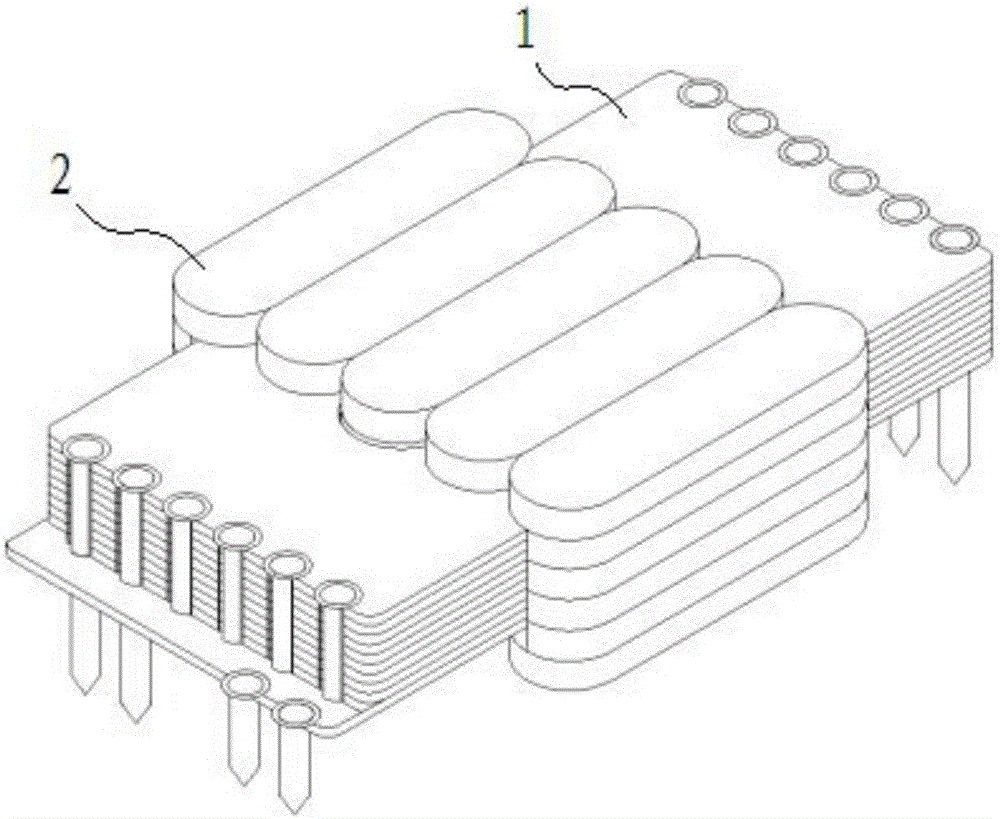
[0025] Such as figure 1 As shown, the planar transformer mainly includes a magnetic core 1 and a coil winding 2 . The magnetic core 1 and the coil winding 2 are mounted together.

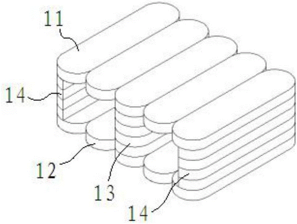
[0026] Such as figure 2 As shown, the magnetic core 1 includes a top plate 11, a bottom plate 12, a center column 13 and a side column 14, the side column 14 has two ends located between the top plate 11 and the bottom plate 12, and the center column 13 is located between the top plate 11 and the bottom plate 12 in the middle. The magnetic core 1 is formed by stacking unit magnetic blocks, and the unit magnetic blocks are fixed together by dispensing glue. The unit magnetic block is a fla...


PUM


Abstract

The invention discloses a planar transformer which comprises a magnetic core and a coil winding; the magnetic core comprises a top plate, a bottom plate, a middle column and two edge columns, the middle column and the two edge columns are located between the top plate and the bottom plate, the coil winding and the magnetic core are assembled together, the top plate and the bottom plate are composed of a whole magnetic block or formed by laying and splicing a plurality of unit magnetic block bodies, and the middle column and the edge columns are formed by stacking multiple unit magnetic block bodies; each unit magnetic block body is a flat strip-shaped block body, and a preset gap is formed between the two ends of the two adjacent unit magnetic block bodies which are laid and spliced. The whole magnetic core is formed by piling multiple unit magnetic block bodies, the transformer can still maintain high efficiency under high frequency, the unit magnetic block body is the flat strip-shaped block body, it is convenient to produce the magnetic core, it is beneficial to miniaturization and planarizartion, and a piled production mode is more beneficial to automated generation; the preset gap is formed between the two ends of the two adjacent unit magnetic block bodies which are laid and spliced, magnetic resistance between every two unit magnetic block bodies is increased, an edge magnetic line can be drawn close to the magnetic core, and thus diffusion flux is reduced.

Description

technical field [0001] The present application relates to a planar transformer. Background technique [0002] With the continuous development of electronic information technology, transformers are one of the key components in electronic equipment. Since the advent of planar transformers, they have been used in communications, notebook computers, automotive electronics, digital televisions, etc. in just over 10 years. be widely used. The higher and higher requirements make planar transformers become the mainstream and trend of the transformer industry. [0003] The planar transformer is a kind of planar structure transformer developed by the electronic transformer after a long period of development. From the appearance point of view, the biggest difference compared with the traditional transformer lies in the iron core and coil winding. The planar transformer winding is formed by etching the copper foil on the PCB board and stacking it spirally by using the PCB board manuf...

Claims


Application Information

Patent Timeline
Patent Type & Authority Applications(China)
IPC IPC(8): H01F27/24H01F27/26H01F27/28H01F27/30
CPCH01F27/24H01F27/263H01F27/2804H01F27/306H01F2027/2809H01F2027/2819
Inventor 朱勇谢明华王弢
Owner SHENZHEN MAIJIRUI TECH CO LTD
Why Eureka
Try Eureka