
Biomass downdraft type gasification air and heat supply system

A heating system and gasification system technology, applied in the field of stoves, can solve the problems of low utilization rate of calorific value, incomplete gasification, inconvenient use of stoves, etc., and achieve high energy conversion efficiency, scientific and compact structure, and full use of space. Effect

Inactive Publication Date: 2016-08-31
周勇
View PDF7 Cites 20 Cited by
  • Summary
  • Abstract
  • Description
  • Claims
  • Application Information

AI Technical Summary

Problems solved by technology

[0002] my country is a large agricultural country, and there is sufficient biomass energy such as firewood and straw. In the development and utilization of biomass energy, the common method is direct combustion or gasification power generation. However, when direct combustion is used, fuelwood needs to be added to the stove frequently. , inconvenient to use, gasification power generation is limited by cost, poor economic benefits, and cannot be widely applied
Traditional stoves have a long history of using firewood and straw. Traditional stoves are inconvenient to use and have a low utilization rate of calorific value, generally only 15% to 20%, which causes serious air pollution.
It is also gradually abandoned in the vast rural areas, resulting in less and less development and utilization of biomass energy, and cannot effectively utilize a large amount of renewable firewood and straw in rural areas
[0003] For this reason, a small-scale ash removal and dust removal system device for gasifying biomass such as firewood and straw into combustible gas and a biomass gasification gas supply and heating system using this device came into being. However, there are some defects in the updraft gasification stove: (1) the high tar content leads to the short life of the gasification stove, and even if the filter is added, the problem of difficult maintenance will appear; ( 2) The gas production is unstable, and the gasification of biomass is difficult to control, which greatly affects the promotion of gasification stoves; (3) The calorific value of gas production is low, and the biomass gasification is not sufficient, so that the calorific value of gas production cannot reach daily use Require
However, in the follow-up improvement process of the inventor, many defects were still found: a single fan makes the total power of the stove difficult to meet the requirements of daily life; Poor thermal expansion and contraction performance, incomplete gasification, insufficient internal temperature of the gasification furnace core, insufficient pyrolysis reaction of tar, incomplete removal of tar and other defects, resulting in unsatisfactory gas production stability of biomass fuels such as firewood and straw ;In the process of use, there are often foreign objects, such as stones, iron nails, and coked pieces of ashes, and the small holes of the grate cannot pass through at all. After a long time, the gasifier will produce unstable gas, or even completely fail; in actual use Inconvenient, hindering its popularization and application
However, in the subsequent use process, it was found that there are still some defects when it is used in industry: (1) The feeding is not automated, and it takes a lot of manpower and high labor costs when used in industry; (2) Furnace core row The ash content cannot be automated, and it is difficult to connect with industrial automation; (3) The ash and dust content in the gasification gas is high, which is not clean and environmentally friendly, and is not suitable for large-scale industrial use; (4) The waste heat of the gasification reaction is not fully utilized, and the gasification The high temperature heat in the air is not fully utilized

Method used


Image

  • Biomass downdraft type gasification air and heat supply system
  • Biomass downdraft type gasification air and heat supply system
  • Biomass downdraft type gasification air and heat supply system

Examples


Embodiment Construction

[0037] The present invention and its beneficial technical effects will be further described in detail below in conjunction with the accompanying drawings and preferred embodiments.

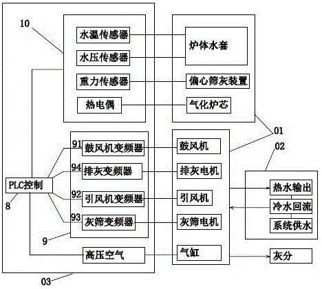
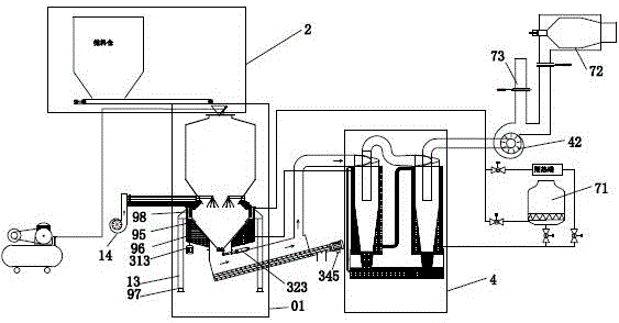
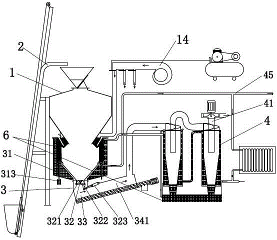
[0038] see figure 1 ~ Figure 9 , The biomass downdraft gasification gas supply and heating system 02 includes a gasification system 01 that converts biomass fuel into combustible gas, and a heating system that recovers waste heat in the production process of the gasification system 01 and supplies heat to the outside 02, and the control system 03 that coordinates the work of the gasification system 01 and the heating system 02; the gasification system 01 includes a feed system 2 that automatically adds biomass fuel to the gasification reduction system 1, and converts the biomass fuel into combustion gas The gasification reduction system 1, the ash discharge and slagging system 3 that discharges the solid components generated by the gasification reduction system 1, the dust removal and cooling s...


PUM


Abstract

The invention discloses a biomass downdraft type gasification air and heat supply system which comprises a gasification system, a heat supply system and a control system. The gasification system comprises a feeding system, a gasification reduction system, an ash discharge deslagging system and a dust removal cooling system. The heat supply system comprises a waste heat recycling hot water system and a cooling system. The feeding system, the gasification reduction system and the ash discharge deslagging system are sequentially connected from top to bottom. The dust removal cooling system is connected with the ash discharge deslagging system. The hot water system is arranged on the periphery of the gasification system and the dust removal cooling system. The cooling system is connected with the hot water system. The biomass downdraft type gasification air and heat supply system has the advantages that the complete gasification and heat supply system is formed, scientific planning is performed, and the clean and environment-friendly automatic air and heat supply system is formed. The sub devices are scientific and compact in structure, the automatic level is high, use is convenient, gas is produced efficiently, the outlet gas is clean and low in temperature, and energy conservation and environmental protection are achieved; the positive pushing effect is achieved for extended application of renewable biomass energy.

Description

technical field [0001] The invention relates to a cooker, in particular to a gasification combustion cooker using biomass raw materials such as firewood and straw as fuel. Background technique [0002] my country is a large agricultural country, and there is sufficient biomass energy such as firewood and straw. In the development and utilization of biomass energy, the common method is direct combustion or gasification power generation. However, when direct combustion is used, fuelwood needs to be added to the stove frequently. , it is inconvenient to use, gasification power generation is limited by the cost, and the economic benefits are not good, so it cannot be widely applied. Traditional stoves have a long history of using firewood and straw. Traditional stoves are inconvenient to use and have a low utilization rate of calorific value, generally only 15% to 20%, which causes serious air pollution. It is also gradually abandoned in the vast rural areas, resulting in less a...

Claims


Application Information

Patent Timeline
IPC IPC(8): C10J3/20C10J3/30C10J3/34C10J3/72C10J3/84C10J3/76
CPCC10J3/20C10J3/30C10J3/34C10J3/723C10J3/725C10J3/76C10J3/84C10J2300/0916C10J2300/0956C10J2300/16C10J2300/1603Y02P20/129
Inventor 周勇
Owner 周勇
Learn More