Frequency conversion measurement circuit for over-excitation protection and over-excitation protection method

A technology of overexcitation protection and measurement circuit, applied in the magnetic measurement environment, measurement of magnetic variables, measurement devices, etc., can solve the problems of large ts error, slow calculation speed, long protection action and return time, etc.

Active Publication Date: 2016-08-24
NANJING GUODIAN NANZI POWER GRID AUTOMATION CO LTD
View PDF5 Cites 3 Cited by
  • Summary
  • Abstract
  • Description
  • Claims
  • Application Information

AI Technical Summary

Problems solved by technology

[0004] (1) Since the zero-crossing point of the waveform must be measured, the protection calculation time is related to the frequency. The smaller the frequency, the longer the data window, the slower the calculation speed, the longer the inherent delay, and the shorter the protection action and return time. long;
[0005] (2) When measuring the zero-crossing point, for the case where the zero-crossing point is a non-sampling point, it needs to be simulated by interpolation method, and there is an error in frequency measurement;
[0006] (3) When calculating the waveform integral value, the trapezoidal fitting algorithm is generally used, and there are errors in the calculation results
[0009] (1) The action time limit ts calculated by the broken line method does not change smoothly near the fitting point. When the overexcitation value has a small shake, the calculated ts has a large error and often cannot meet the time accuracy requirements;
[0010] (2) The time criterion is established under the condition that the overexcitation value entering the inverse time limit curve remains static, while the actual overexcitation value changes dynamically. If the influence of the historical overexcitation value is not considered, it will bring uncertainty time offset

Method used


Image

  • Frequency conversion measurement circuit for over-excitation protection and over-excitation protection method
  • Frequency conversion measurement circuit for over-excitation protection and over-excitation protection method
  • Frequency conversion measurement circuit for over-excitation protection and over-excitation protection method

Examples


Embodiment Construction

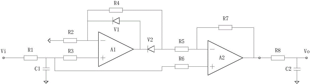
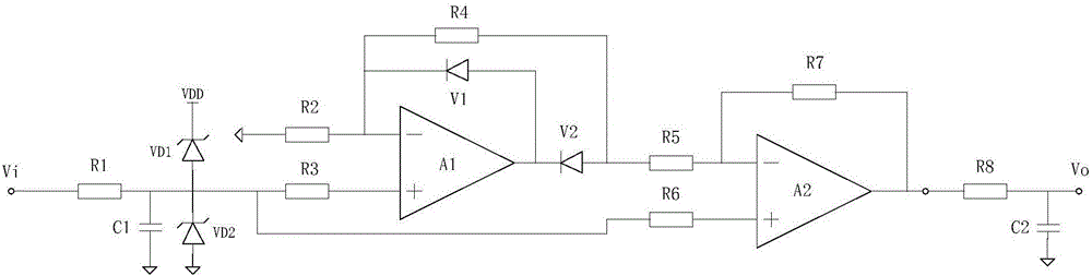
[0045] The present invention will be further described below in conjunction with the accompanying drawings. The following examples are only used to illustrate the technical solution of the present invention more clearly, but not to limit the protection scope of the present invention.

[0046] like figure 1 As shown, the frequency conversion measurement circuit for overexcitation protection provided by the present invention includes power supply VDD, ground GND, operational amplifier A1, operational amplifier A2, diode V1, diode V2, sampling resistor R1, sampling capacitor C1, resistor R2, Resistor R3, resistor R4, resistor R5, resistor R6, resistor R7, filter resistor R8 and filter capacitor C2; the signal to be measured Vi is connected to one end of the sampling resistor R1, and the other end of R1 is grounded to GND through the sampling capacitor C1 and connected to the resistor R3 To the positive input terminal of the operational amplifier A1, through the resistor R6 and t...


PUM


Abstract

The present invention provides a frequency conversion measurement circuit for over-excitation protection and an over-excitation protection method. The circuit can measure the multiples of over-excitation in real time, has high conversion speed and high precision, and is just slightly affected by frequency with appropriate circuit parameters provided. Since judgment on a zero crossing point is not required, the inherent delay of the protection is short, and therefore, requirements of the over-excitation protection for action time and return time can be satisfied; and a temperature compensation circuit is adopted, so that accuracy error caused by temperature variation can be effectively prevented. According to the over-excitation protection method, the frequency conversion measurement circuit is adopted to convert signals to be tested into direct current voltage signals, and the direct current voltage signals are outputted; modes for judging whether the protection acts are flexible, hardware can be used to directly judge whether the protection acts, and software can be also used to indirectly judge whether the protection acts; a plurality of parabolas are adopted to fit an inverse-time curve, so that the problem of unsmooth time variation on fitting points can be solved; and a heat effect accumulation discrimination algorithm is adopted, so that the cumulative effect of historical values in an over-excitation value dynamic variation process can be reflected.

Description

technical field [0001] The invention relates to a frequency conversion measurement circuit for over-excitation protection and an over-excitation protection method, belonging to the technical field of relay protection for main equipment in a power system. Background technique [0002] In the protection of large and medium-sized generators or transformers in power systems, the inverse time overexcitation protection is a must-have protection to prevent overheating of the iron core caused by overexcitation. Conventional inverse time overexcitation protection usually uses software calculation method to realize the measurement of overexcitation multiple, which is generally realized by the following method: introduce voltage through voltage transformer, sample voltage signal to obtain instantaneous voltage value, and digitally calculate voltage U value and frequency respectively Measure the f value, and then synthesize and calculate the U / f value; or measure the zero-crossing point...

Claims


Application Information

Patent Timeline
IPC IPC(8): G01R33/00
CPCG01R33/00G01R33/0082
Inventor 包明磊徐业荣桑建斌李明
Owner NANJING GUODIAN NANZI POWER GRID AUTOMATION CO LTD
Why Eureka
Try Eureka