A kind of graphene electro-optic modulator and preparation method thereof

An electro-optic modulator and graphene technology, applied in the field of optical modulation, can solve the problems of limiting the application of graphene electro-optic modulators, large insertion loss of waveguides, etc., and achieve controllable pulse repetition frequency, tunable pulse width, and carrier migration high rate effect

Active Publication Date: 2019-01-18
NORTHWEST UNIV
View PDF5 Cites 0 Cited by
  • Summary
  • Abstract
  • Description
  • Claims
  • Application Information

AI Technical Summary

Problems solved by technology

At present, the technology based on graphene electro-optic modulation mainly uses the waveguide as the carrier to couple the modulated light. Applications
Active Q-switching devices based on graphene electro-optic modulation that do not rely on waveguide structures have not appeared in the prior art

Method used


Image

  • A kind of graphene electro-optic modulator and preparation method thereof
  • A kind of graphene electro-optic modulator and preparation method thereof
  • A kind of graphene electro-optic modulator and preparation method thereof

Examples


preparation example Construction

[0041] The preparation process of the innovative graphene electro-optic modulator of the present invention is further provided below, and the preparation method of the graphene electro-optic modulator comprises the following steps:

[0042] Step 1. Clean the optical substrate:

[0043] First, immerse the quartz plate as an optical substrate in acetone (Acetone) solvent for ultrasonic cleaning for 5 minutes, then immerse in isopropanol (Isopropanol) solvent for ultrasonic cleaning for 5 minutes, and finally use a nitrogen gun to remove the isopropanol remaining on the surface of the quartz plate (Isopropanol) and blow dry.

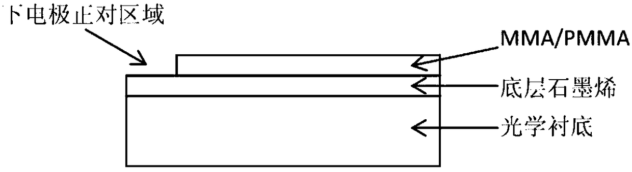
[0044] Step 2. Transfer the underlying graphene film:

[0045] Firstly, polymethyl methacrylate (PMMA) is spin-coated on the surface of the copper foil with the graphene layer; after the PMMA is air-dried, the graphene grown on the back of the copper foil is etched clean using reactive ion etching (RIE) Then cut two copper foils with graphene attached on ...

Embodiment 1

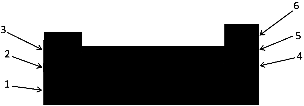
[0060] A graphene electro-optic modulator, its optical microscopic image is attached Figure 15 As shown, it includes an optical substrate 1, a bottom graphene 2, a lower metal electrode 3, an insulating layer 4, a top graphene 5 and an upper metal electrode 6 from bottom to top, and the top graphene 5 and the bottom graphene 2 are arranged oppositely, At the same time, there is no top-layer graphene 5 directly above the lower metal electrode 3, and no bottom-layer graphene directly below the upper metal electrode 6. The optical substrate 1 is a 2*2cm double-sided polished quartz sheet with a small insertion loss, and the top layer of graphite Both the graphene 5 and the bottom graphene 2 are made of single-layer graphene, and the single-layer graphene is grown on the copper foil substrate by chemical vapor deposition, and the lower metal electrode 3 and the upper metal electrode 6 are both Ti / Au with a thickness of 5 / 50nm. The distance between the two electrodes is 500 μm. T...


PUM

PropertyMeasurementUnit
thicknessaaaaaaaaaa
thicknessaaaaaaaaaa
thicknessaaaaaaaaaa

Abstract

The invention proposes a graphene electro-optical modulator and a preparation method thereof. The graphene electro-optical modulator has a flat capacitive structure, including an optical substrate, a bottom layer of graphene, an insulating layer and a top layer of graphene. The bottom layer of graphene is located on the optical lining. On the bottom, the insulating layer is on the bottom graphene, the top graphene is on the insulating layer, the top graphene and the bottom graphene are insulated from each other through the insulating layer, and the top graphene is above the bottom graphene, and the external modulation voltage is applied to the bottom layer graphene and top graphene. The graphene electro-optic modulator of the present invention is an active Q-switched device based on graphene electro-optic modulation technology that does not rely on a waveguide structure. It changes the modulation depth by applying amplitude changes of periodic voltage, and can adapt to the changes in light modulation depth caused by different laser parameters. In order to meet the demand, inserting the graphene electro-optical modulator into a laser can obtain pulse laser output with large pulse energy and controllable repetition frequency, which has broad market prospects.

Description

technical field [0001] The present invention relates to the technical field of light modulation, in particular to a graphene electro-optic modulation-based broadband active Q-switching device, in particular to a graphene electro-optic modulator and a preparation method thereof. Background technique [0002] Graphene is a sp 2 A one-atom-thick two-dimensional crystal composed of hybridized carbon atoms. Due to its unique atomic arrangement and energy band structure, graphene not only exhibits an ultra-fast optical response rate, but also has a constant absorption rate of 2.3% for the visible to mid-infrared band; in addition, the graphene carrier concentration can be determined by chemical atomic doping or electrical doping, wherein the excellent controllability of electrical doping provides a theoretical and technical basis for the application of graphene in photoelectric modulation devices, therefore, the development of electro-optic modulators based on graphene materials,...

Claims


Application Information

Patent Timeline
Patent Type & Authority Patents(China)
IPC IPC(8): G02F1/03
CPCG02F1/0305G02F1/0316
Inventor 任兆玉孙志培祁媚薛晖李雕白晋涛
Owner NORTHWEST UNIV
Why Eureka
Try Eureka