
a grouting system

A technology of grouting system and grouting pipe, which is applied in the field of grouting system for bored pile grouting, which can solve problems such as uneven settlement of pile group foundation, inconvenient operation, and reduced pile side resistance, so as to avoid local collapse , easy control and simple structure

Inactive Publication Date: 2017-12-26
HENAN POLYTECHNIC UNIV
View PDF6 Cites 0 Cited by
  • Summary
  • Abstract
  • Description
  • Claims
  • Application Information

AI Technical Summary

Problems solved by technology

[0002] Bored cast-in-place pile is the most common pile type, but in the application process of bored cast-in-place pile, there is mud skin on the side of the pile that affects the performance of side resistance. In the grouting port method, after the grout flows out from the grouting port, the sediment at the bottom of the pile is reinforced through the free flow of the grouting liquid. However, due to the uneven height of the pile bottom, the grout flow is often cut off and cannot reach the position where grouting is required. There is some unreinforced sediment at the bottom of the pile, which affects the performance of end rent. Due to differences in construction level, different thickness of sediment, and local differences in geological conditions, the vertical bearing capacity of large-area engineering piles on the same construction site is scattered, which may lead to pile group foundations. Uneven settlement, volume shrinkage of the pile body concrete after consolidation, gap between the pile body concrete and the wall of the borehole, resulting in reduced pile side resistance, interruption of grouting, grouting, blockage of the grouting pipe, and loss of grout, In response to the above problems, some grouting systems have been developed, but most of the existing systems are complex in structure and inconvenient to operate

Method used


Image

  • a grouting system
  • a grouting system
  • a grouting system

Examples


Embodiment Construction

[0022] Below in conjunction with accompanying drawing and specific embodiment the present invention is further described:

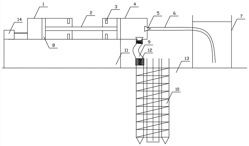
[0023] Such as Figure 1-Figure 6 As shown, when in use, the hydraulic pump 14 sucks hydraulic oil from the hydraulic cylinder 1, pulls the piston 8 in the hydraulic cylinder 1, the hydraulic rod 2, and the piston 8 in the material cylinder 4 to move, and is installed at the interface between the slurry suction pipe 6 and the material cylinder 4 The baffle plate 55 of the one-way valve 5 at the place is on the material cylinder 4 side, and the material of the spool 53 is cast iron. The suction force of the piston 8 overcomes the suction force of the magnet 52 and the elastic force of the rubber band 54 to do work, so that the spool 53 approaches the baffle plate 55. End movement, the slurry in the slurry tank 7 is injected into the material cylinder 4 through the gap between the hole wall of the conical through hole 56 and the valve core 53 to realize slu...


PUM


Abstract

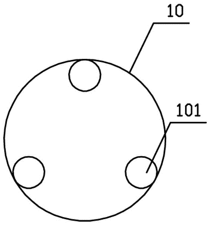
The invention relates to a grouting system which comprises a hydraulic cylinder, a grout cylinder, a grout pool, a support and a hydraulic pump. The hydraulic cylinder and the grout cylinder are horizontally arranged on the support. The front end of the hydraulic cylinder is connected with the hydraulic pump. The rear end of the hydraulic cylinder is connected with the grout cylinder. A piston and a stop ring are arranged in the hydraulic cylinder, and a piston and a stop ring are arranged in the grout cylinder. The piston in the hydraulic cylinder is connected with the piston in the grout cylinder through a piston rod. The grout pool is arranged at the rear end of the grout cylinder. The grout cylinder and the grout pool are connected through a grout sucking pipe. A reinforcement cage is arranged at the lower portion of the grout cylinder and is arranged in a soil body. The reinforcement cage is formed by bundling grouting pipes and reinforcing steel bars, the three grouting pipes are arranged in the reinforcement cage, and the angle between every two adjacent grouting pipes in the three grouting pipes is 120 degrees. The grout cylinder is connected with the grouting pipes through grouting hoses. A nozzle is arranged at the lower portion of each grouting pipe. A one-way valve is arranged at the position of a connecting opening of each grouting pipe and the grout cylinder, and a one-way valve is arranged at the position of a connecting opening of each grouting hose and the grout cylinder. The grouting system is simple in structure, durable, convenient to use and good in use effect.

Description

technical field [0001] The invention relates to a grouting system, in particular to a grouting system for bored pile grouting. Background technique [0002] Bored cast-in-place pile is the most common pile type, but in the application process of bored cast-in-place pile, there is mud skin on the side of the pile that affects the performance of side resistance. In the grouting port method, after the grout flows out from the grouting port, the sediment at the bottom of the pile is reinforced through the free flow of the grouting liquid. However, due to the uneven height of the pile bottom, the grout flow is often cut off and cannot reach the position where grouting is required. There is some unreinforced sediment at the bottom of the pile, which affects the performance of end rent. Due to differences in construction level, different thickness of sediment, and local differences in geological conditions, the vertical bearing capacity of large-area engineering piles on the same c...

Claims


Application Information

Patent Timeline
Patent Type & Authority Patents(China)
IPC IPC(8): E02D15/04
CPCE02D15/04
Inventor 谢国强房玉中李建委杨锋王建军赫中营
Owner HENAN POLYTECHNIC UNIV
Learn More