
A three-band microstrip pifa antenna

An antenna and microstrip technology, which is applied in the field of three-band microstrip PIFA antennas, can solve the problems of limited and single frequency modes, unused space, etc., and achieve the effect of size reduction

Inactive Publication Date: 2018-06-26
XI AN JIAOTONG UNIV
View PDF5 Cites 0 Cited by
  • Summary
  • Abstract
  • Description
  • Claims
  • Application Information

AI Technical Summary

Problems solved by technology

In the prior art, in order to achieve the purpose of antenna multi-frequency work, the method of slotting on the antenna patch is often used, but there are also some shortcomings: 1. More use of a single slot number and structure, which can arouse The frequency mode is limited, and the method of multi-slot to achieve multi-frequency antenna has not been deeply explored; 2. The space between the radiation patch and the floor is not used in the middle layer of the medium

Method used


Image

  • A three-band microstrip pifa antenna
  • A three-band microstrip pifa antenna
  • A three-band microstrip pifa antenna

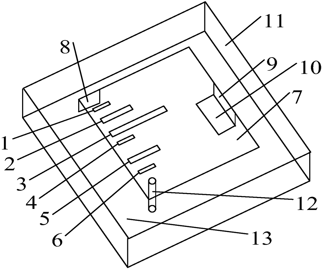
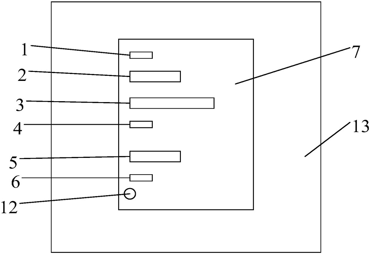
Examples


Embodiment Construction

[0023] The present invention will be further described in detail below in conjunction with specific embodiments, which are explanations of the present invention rather than limitations.

[0024] A three-band microstrip PIFA antenna of the present invention can excite the frequency by opening a group of six elongated slot lines on the radiation patch 7 and respectively opening them at the antinodes of the electric field wave in the corresponding frequency mode. model. In the present invention, by the boundary condition that the antenna radiation side is short-circuited and open-circuited at the same time, the corresponding excited mode frequency f n and the dominant mode frequency f when not slotted 0 Corresponding relationship:

[0025] f n =(2n+1)f 0 ;

[0026] The distance between the antinode position of each standing wave and the short-circuit side is an odd multiple of a quarter wavelength. The short-circuit side is the short side connected to the short-circuit surf...


PUM


Abstract

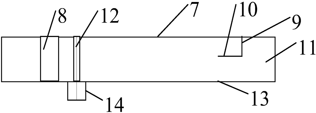
The invention provides a three-frequency-band microstrip PIFA antenna which can accurately activate three frequency modes of an antenna. The three-frequency-band microstrip PIFA antenna has advantages of simple structure, reasonable design and small size. The three-frequency-band microstrip PIFA antenna comprises the components of a radiation patch, a shortcircuit surface, a connecting surface, a foldable patch, a dielectric layer, an electric feeding probe and a grounding board One long side of the rectangular radiation path is provided with six parallel elongated slot wires. One end of each of the six elongated slot wires is aligned with one end of each of the other elongated slot wires, and furthermore equal distance between one end of each of the six elongated slot wires and the long side which is adjacent to the radiation path is realized. The upper surface of the dielectric layer is provided with the radiation patch, and the lower surface is provided with the grounding board. The grounding board is provided with an SMA joint. The SMA joint is connected with the radiation path for realizing electric feeding through the electric feeding probe which penetrates through the dielectric layer. The electric feeding probe and the elongated slot wires are arranged at the same side. The shortcircuit surface is vertically arranged on a short side of the radiation patch and is connected with the grounding board. The foldable path is arranged in the dielectric layer in a manner of parallel with the radiation patch. The connecting surface is vertically arranged on the long side which is far from the elongated slot wires on the radiation patch. The two ends of the connecting surface are respectively connected with the radiation path and the foldable patch.

Description

technical field [0001] The invention relates to the technical field of wireless antennas, in particular to a three-band microstrip PIFA antenna. Background technique [0002] PIFA antennas are evolved from ordinary microstrip patch antennas and are widely used in terminals of communication systems. In the prior art, in order to achieve the purpose of antenna multi-frequency work, the method of slotting on the antenna patch is often used, but there are also some shortcomings: 1. More use of a single slot number and structure, which can arouse The frequency mode is limited, and the method of multi-slot to achieve multi-frequency of the antenna has not been deeply explored; 2. The space of the medium layer between the radiation patch and the floor has not been utilized. Therefore, it is necessary to make further improvements to the multi-band microstrip PIFA antenna. Contents of the invention [0003] Aiming at the problems existing in the prior art, the present invention p...

Claims


Application Information

Patent Timeline
Patent Type & Authority Patents(China)
IPC IPC(8): H01Q1/38H01Q1/48H01Q1/50H01Q5/28H01Q5/307
CPCH01Q1/38H01Q1/48H01Q1/50H01Q5/28H01Q5/307
Inventor 冯恩信白杨
Owner XI AN JIAOTONG UNIV
Learn More