Eureka AIR delivers breakthrough ideas for toughest innovation challenges, trusted by R&D personnel around the world.

Controllable thermal infrared induction type LED ceiling lamp

An LED ceiling lamp, thermal infrared technology, applied in the direction of electric lamp circuit layout, lighting device, light source, etc., can solve the problem of long-term opening and so on

Inactive Publication Date: 2014-06-04
XIAN SINENG NETWORK SCI & TECH
View PDF0 Cites 0 Cited by
  • Summary
  • Abstract
  • Description
  • Claims
  • Application Information

AI Technical Summary

Problems solved by technology

However, in some cases, it needs to be turned on for a long time, and in some cases it needs to be activated by induction. The existing thermal infrared induction LED lights cannot achieve this function.

Method used


Image

  • Controllable thermal infrared induction type LED ceiling lamp
  • Controllable thermal infrared induction type LED ceiling lamp

Examples


Embodiment Construction

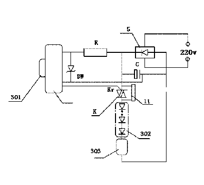
[0014] Such as figure 1 As shown, a controllable thermal infrared induction LED ceiling lamp includes a housing 1, the housing 1 is structured as a screw 9, the housing 1 has a control circuit 3 and a lamp board 8, and the control circuit 3 is connected to a pyroelectric sensor 2. The sensing surface of the pyroelectric sensor 2 corresponds to the sensing port 10 of the casing 1, so that the thermal infrared signal can be sensitively received through the sensing port 10 when the human body moves. The lamp board 8 is distributed with LEDs 7 connected in series, the rectifier circuit 5 is inside the screw port 9, and the 220v alternating current is output to the control circuit 3 and the lamp board 8 after being rectified by the rectifier circuit 5 .

[0015] Such as figure 2 As shown, the control circuit 3 includes: a thermal infrared circuit 301, an LED lamp string 302 and a drive circuit 303. The output end of the rectifier circuit 5 is divided into two circuits, one is ele...


PUM


Abstract

The invention relates to an LED ceiling lamp, in particular to a controllable thermal infrared induction type LED ceiling lamp. The controllable thermal infrared induction type LED ceiling lamp is characterized in that the LED ceiling lamp comprises a shell, a control circuit and a lamp panel are arranged in the shell, the control circuit is connected with a pyroelectric sensor, the induction face of the pyroelectric sensor corresponds to an induction opening of the shell, LEDs connected in series are distributed on the lamp panel, and in a threaded opening of the rectifying circuit, the 220 v alternating current is output to the control circuit and the lamp panel after being rectified through the rectifying circuit.

Description

technical field [0001] The invention relates to an LED ceiling lamp, in particular to a thermal infrared induction LED ceiling lamp. Background technique [0002] The existing thermal infrared induction LED ceiling lamp is automatically turned on through thermal infrared induction, which combines power saving and lighting, and is particularly convenient in some infrequently used environments. For example, on balconies and corridors, this kind of sensor light has a delay circuit. After working for a short period of time, it will be turned off unless someone walks and turns it on again to achieve the effect of power saving. However, in some cases, it needs to be turned on for a long time, and in some cases, it needs to be activated by induction, and the existing thermal infrared induction LED lamps cannot achieve this function. Contents of the invention [0003] The purpose of the present invention is to provide a dual-function controllable thermal infrared induction LED ce...

Claims


Application Information

Patent Timeline
Patent Type & Authority Applications(China)
IPC IPC(8): H05B37/02
Inventor 王小娜
Owner XIAN SINENG NETWORK SCI & TECH
Why Eureka
Eureka Blog
Learn More