
Turbo generator set vibration fault diagnosis method based on forward reasoning

A technology for steam turbine generator set and fault diagnosis, which is used in engine testing, data processing applications, electrical digital data processing, etc., and can solve problems such as low accuracy, compiled into computer language, and unreliable diagnosis results.

Active Publication Date: 2016-08-10
XIAN XIRE VIBRATION INST CO LTD
View PDF5 Cites 17 Cited by
  • Summary
  • Abstract
  • Description
  • Claims
  • Application Information

AI Technical Summary

Problems solved by technology

However, the reliability of the diagnostic results of the above-mentioned existing vibration fault diagnosis system mainly depends on the expert experience and thinking mode, that is, the thinking mode and process of expert diagnosis are followed, and the diagnosis is carried out based on the expert's fault knowledge base. The thinking mode and process are compiled into the language of the computer, and the R&D personnel have encountered difficulties. Therefore, no matter whether the expert system installed and used is imported or domestic, the diagnostic results are not credible. Therefore, after the diagnostic system is put into operation, no one Therefore, the service life of these diagnostic systems in power plants generally does not exceed 3 years, and they are finally forgotten and discarded
[0004] After analysis, it is found that the diagnosis results of the existing online vibration fault diagnosis system have low accuracy and are not credible, mainly due to the following two reasons: First, reverse reasoning is used to diagnose faults, although the online vibration fault diagnosis systems developed by various companies use the The specific diagnostic methods are different, including the use of neural networks, fuzzy theory, mathematical models to calculate the credibility of symptoms, system self-learning functions, etc., but the diagnostic thinking mode is carried out by reverse reasoning; reverse reasoning is also called target direct Inference, it deduces vibration faults based on vibration characteristics; however, since the relationship between vibration characteristics and faults is not a simple one-to-one correspondence, but multiple cross-relationships, it is inevitable that misdiagnosis and missed diagnosis will occur during the reverse reasoning process, such as At present, all diagnostic systems diagnose one of the important faults, rotor misalignment, based on whether the vibration signal contains 2X (that is, twice the frequency) vibration as a sufficient criterion, but there are 5 to 6 reasons for the actual unit to produce 2X vibration faults When the system detects a 2X vibration component, it makes a diagnosis of rotor misalignment before giving a judgment value standard and excluding other 2X vibration faults. This obviously has loopholes and makes the diagnosis result unreliable; 2. The diagnostic criterion is unreliable. The current online diagnostic fault judgment basis is based on the vibration characteristics listed in the traditional textbooks, many of which have major misunderstandings, such as the actual cause of vibration faults that cause 2X (2-fold frequency) vibration There are as many as 5 to 6 types, and 2X vibration is almost always used as the only criterion for rotor misalignment (unit vibration is the most common) fault in online diagnosis; obviously, if this fault feature is used as the criterion, the diagnosis result cannot be in line with reality, so In the case of unreliable criteria, the diagnostic results made are clearly unreliable

Method used


Image

  • Turbo generator set vibration fault diagnosis method based on forward reasoning
  • Turbo generator set vibration fault diagnosis method based on forward reasoning

Examples


Embodiment Construction

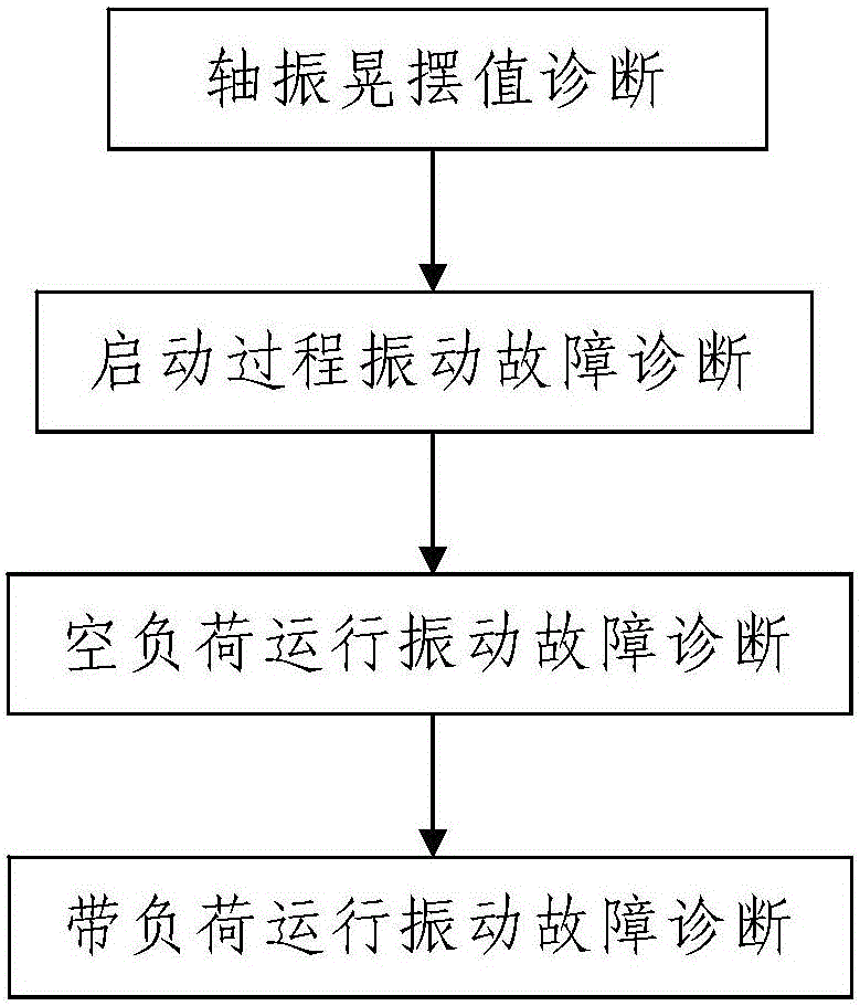
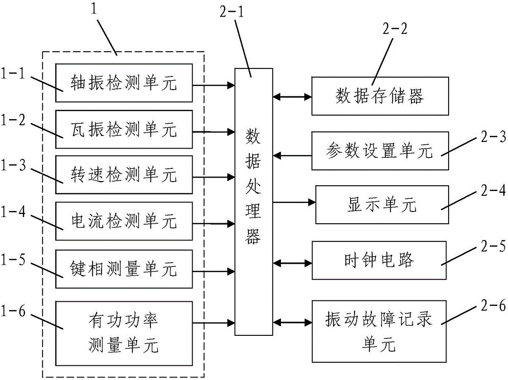
[0096] Such as figure 1 A vibration fault diagnosis method for a turbogenerator set based on forward reasoning is shown. After each startup and operation of the diagnosed turbogenerator set, the parameter detection device 1 is used to check the correlation between the startup and operation of the diagnosed turbogenerator set. The working parameters are detected in real time and the detection information is synchronously transmitted to the vibration fault diagnosis device 2 for automatic vibration fault diagnosis; the parameter detection device 1 includes a rotor working state for real-time detection of the working state of each rotor in the diagnosed steam turbine generator set Detection unit, speed detection unit 1-3 for real-time detection of the rotational speed of the diagnosed turbo-generator set, active power measurement unit 1-6 for measuring the active power of the diagnosed turbo-generator set, The key phase measurement unit 1-5 for the unit to measure the key phase a...


PUM


Abstract

The invention discloses a turbo generator set vibration fault diagnosis method based on forward reasoning. After a diagnosed turbo generator set starts, a parameter detection device is employed to carry out real-time detection on related work parameters in a start and operation process of the diagnosed turbo generator set and synchronously sends the detection information to a vibration fault diagnosis device for automatic vibration fault diagnosis, vibration faults of the diagnosed turbo generator set are diagnosed level by level by the vibration fault diagnosis device according to the detection result transmitted by the parameter detection device in combination with the active power value of the diagnosed turbo generator set, and the fault diagnosis process comprises steps of 1, shaft vibration swinging value diagnosis; 2, start process vibration fault diagnosis; 3, zero load operation vibration fault diagnosis; and 4, loaded operation vibration fault diagnosis. The method is advantaged in that the steps are simple, and the method is reasonable in design, is convenient to realize, has good use effects, can conveniently and rapidly accomplish the online steam turbine vibration fault diagnosis process and can further realize accurate and reliable diagnosis results.

Description

technical field [0001] The invention belongs to the technical field of steam turbine fault diagnosis, and in particular relates to a vibration fault diagnosis method of a steam turbine generator set based on forward reasoning. Background technique [0002] The steam turbine generator set (hereinafter referred to as the steam turbine set) is the most important precision large-scale rotary equipment in a thermal power plant. It is composed of multiple rotors and the working state of each rotor directly affects the production and safety of the power plant. Common faults that directly endanger the safe operation of equipment. In order to eliminate this fault, it is necessary to diagnose the cause of the fault. However, due to the complex mechanism and wide range of vibration faults, it has been a major technical problem for a long time, and vibration faults have always been Plaguing the safe operation of turbogenerator sets. Vibration fault diagnosis is divided into two branche...

Claims


Application Information

Patent Timeline
IPC IPC(8): G01M15/00G06F17/50G06Q50/06
CPCG01M15/00G06Q50/06G06F30/20Y04S10/50
Inventor 施维新施劲波
Owner XIAN XIRE VIBRATION INST CO LTD
Learn More