Circuit for realizing AC input voltage limiting by means of switch mode

A technology of AC input and switch mode, applied in the direction of circuit devices, output power conversion devices, electrical components, etc., can solve the problems of large volume, severe heat generation, low efficiency, etc., and achieve high operation safety, simple circuit design, and small size effect

Active Publication Date: 2016-08-03
NR ELECTRIC CO LTD +1
View PDF4 Cites 3 Cited by
  • Summary
  • Abstract
  • Description
  • Claims
  • Application Information

AI Technical Summary

Problems solved by technology

However, due to the sudden operation of the photovoltaic inverter in island mode, the output AC will instantly rise to 450VAC for 3 cycles, thereby breaking down the power supply input circuit of the electrified control and protection equipment, causing equipment damage and economic losses, and making the photovoltaic system run out of protection
[0003] In rail transit applications, electrification control and protection equipment is powered by the mains. In some applications, when the design of the box transformer transformer is unreasonable, the fluctuation of the primary voltage due to load changes will directly affect the secondary voltage, and the secondary voltage will rise to about 320VAC. , lasting about 30 minutes, long-term overvoltage operation will break down the power supply input circuit of the electrification control protection equipment, causing equipment damage and economic losses, and making the rail transit system run out of protection
[0004] The conventional protection method is to incorporate a silicon chain at the front end of the electrified control and protection equipment, and limit the input voltage through the linear voltage stabilization method of the silicon chain. The disadvantages are large size, low efficiency, severe heat generation, and high cost

Method used


Image

  • Circuit for realizing AC input voltage limiting by means of switch mode

Examples


Embodiment

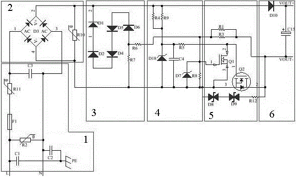
[0043] Such as figure 1 In the shown embodiment, when an AC voltage of 50 Hz is input, it is rectified by D3 and output as a half-wave voltage of 100 Hz. D1 is a 47V regulator, and D2, D4, D5, and D6 are 82V regulators, so the voltage comparison threshold is 375V. R7 is a 3W, 100K ohm power resistor. When the peak value of the input AC voltage is lower than 375V, the comparison circuit is cut off, the gate-source voltage of Q1 is 0V, and Q1 is turned off. D18 is a 16V Zener tube, and the resistance of R4 and R9 is very large, so the voltage across C4 is 16V, that is, the gate-source voltage of Q2 is 16V, and Q2 is turned on. The input AC voltage charges the C15 capacitor and provides energy for the subsequent circuit. When the peak value of the input AC voltage is higher than 375V, for the convenience of description, it is assumed that the peak value of the input AC voltage is 400V. When the 100HZ half-wave voltage rises above 375V, the comparison circuit conducts the actio...


PUM


Abstract

The invention discloses a circuit for realizing AC input voltage limiting by means of a switch mode. The circuit comprises an input circuit module, a rectifier circuit module, a comparison circuit module, a field effect transistor drive circuit module, a switch circuit module and an output circuit module, wherein the input circuit module inputs the AC input voltage, and outputs the AC input voltage to the comparison circuit module after rectification of the rectifier circuit module, and then eventually outputs the AC input voltage through the output circuit module; the field effect transistor drive circuit module and the switch circuit module are connected to a power supply loop between the comparison circuit module and an output end line module; the comparison circuit module is provided with a voltage comparison function by means of setting of a voltage-regulator tube; a voltage signal being less than a voltage comparison threshold value can switch on a load power supply loop; and a voltage signal being greater than the voltage comparison threshold value enables the comparison circuit module to output a switch-on signal so as to drive on / off of MOS switch tubes which are connected with an original power supply loop in serial and to disconnect the power supply loop. The circuit for realizing AC input voltage limiting by means of a switch mode has the advantages of being small in volume, being high in efficiency, being low in caloric power, and being very low in cost.

Description

technical field [0001] The invention relates to the technical field of electrification control and protection equipment at the back stage of protection, in particular to a circuit for realizing AC input voltage limitation by means of a switch, which is used in photovoltaic, rail transit and other occasions where the AC power supply fluctuates greatly. Background technique [0002] In the application of photovoltaic system, when the low-voltage side switch of the box transformer is tripped, the electrification control and protection equipment in the photovoltaic area is powered by the photovoltaic inverter at this moment. However, due to the sudden operation of the photovoltaic inverter in island mode, the output AC will instantly rise to 450VAC for 3 cycles, thereby breaking down the power supply input circuit of the electrified control and protection equipment, causing equipment damage and economic losses, and making the photovoltaic system Run out of protection. [0003] ...

Claims


Application Information

Patent Timeline
Patent Type & Authority Applications(China)
IPC IPC(8): H02M1/34H02J9/06
CPCH02J9/061H02M1/34H02M1/346Y02B70/10
Inventor 王峰杨伟尹春李臣松杨洋冯亚东李响
Owner NR ELECTRIC CO LTD
Why Eureka
Try Eureka