
Preparation method of bending strain sensing fabric with wireless signal transmission function

A bending strain, wireless signal technology, applied in the direction of fabrics, multi-strand fabrics, textiles, etc., can solve the problems of inability to sense the bending deformation of the antenna, the structure is not stable enough, the deformation of the textile structure, etc. Stable and uniform effect of deformation

Inactive Publication Date: 2017-12-12
DONGHUA UNIV
View PDF10 Cites 0 Cited by
  • Summary
  • Abstract
  • Description
  • Claims
  • Application Information

AI Technical Summary

Problems solved by technology

However, the general laminated fabric antenna structure is not stable enough in the bending process, and it is easy to cause interlayer deformation, which makes the textile structure prone to irregular deformation, so that it is impossible to sense the bending deformation of the antenna by monitoring the change of antenna performance.

Method used


Image

  • Preparation method of bending strain sensing fabric with wireless signal transmission function
  • Preparation method of bending strain sensing fabric with wireless signal transmission function
  • Preparation method of bending strain sensing fabric with wireless signal transmission function

Examples


Embodiment 1

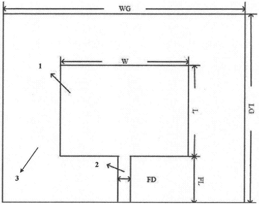
[0035] combine figure 1 , the preparation of the three-dimensional woven structure single radiating element bending sensing antenna fabric, the specific method is as follows:

[0036] (1) Bare copper wire is selected as the conductive yarn with a diameter of 0.5 mm; elastic polyethylene yarn with good dielectric properties is selected with a fineness of 400tex.

[0037] (2) The operating frequency of the antenna is designed to be 1.5GHz, the thickness of the prepared three-dimensional fabric is 2.5mm, and its dielectric constant r=1.5, according to the antenna design theory (see Chapter 6 of "Antenna Theory and Technology", edited by Zhong Shunshi) , the size parameters of the single radiating element microstrip antenna are calculated. figure 1 Among them, W and L are the width and length of the radiating element respectively, WG and LG are the width and length of the finished microstrip antenna, FL is the length of the feeder line, and FD is the width of the feeder line.

...

Embodiment 2

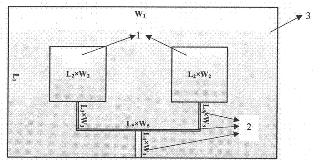
[0043] combine figure 2 , the preparation of the three-dimensional woven structure double radiator bending strain sensing fabric, the specific method is as follows:

[0044] (1) Choose bare copper wire as the conductive yarn, with a diameter of 0.5 mm; choose aramid yarn with good dielectric properties, with a fineness of 400tex.

[0045] (2) The working frequency of the designed antenna is 2 GHz, the thickness of the prepared three-dimensional fabric is 2.5 mm, and its dielectric constant r = 4.5, and the size parameters of the single radiating element microstrip antenna are calculated according to the antenna design theory, as shown in figure 2As shown, where W1 and L1 are the width and length of the sensing fabric, W2 and L2 are the width and length of the radiating element patch respectively, L3, L4, L5 are the lengths of the feeder lines, and W3, W4, W5 are the widths of the feeder lines.

[0046] (3) Weaving the single radiating element microstrip antenna prefab. The...


PUM

PropertyMeasurementUnit
diameteraaaaaaaaaa
thicknessaaaaaaaaaa
elongation at breakaaaaaaaaaa

Abstract

The invention provides a method for preparing a bending strain sensing fabric with a wireless signal transmission function. Firstly, an elastic yarn is selected, woven into a fabric, and used as a dielectric substrate of the antenna, and its dielectric constant and dielectric constant are tested and calculated. Loss; according to the calculation results and the required operating frequency of the antenna, calculate the basic size of the radiation element of the antenna, select a conductive yarn and elastic yarn to weave the radiation element, feeder and grounding plate of the antenna; finally through the vertical binding yarn , each part is formed into an integral fabric antenna structure with obvious frequency changes during bending deformation and linear regularity. The invention combines the bending strain-sensitive textile structure with the antenna element to realize a bending strain sensing fabric with both wireless signal transmission function and bending strain sensing function; The deformation under action is stable, uniform and predictable; the product cost is low and the performance is stable, which is conducive to popularization and use.

Description

technical field [0001] The invention relates to a preparation method of a bending strain sensing fabric with wireless signal transmission function, and belongs to the technical field of functional textiles and intelligent textiles. Background technique [0002] With the rapid development of science and technology, the functions of textiles are not limited to beauty and warmth. On the premise of maintaining their original characteristics, smart textiles have become a trend in their development. In recent years, smart textiles have been It has been widely used in electronics, sports, digital multimedia entertainment, biomedicine and military defense. The combination of textiles and communication equipment has certain research significance. As a kind of smart textiles, wearable antennas combine microstrip antennas with flexible and deformable textiles, which take into account the advantages of both textiles and microstrip antennas. The microstrip antenna has a series of excel...

Claims


Application Information

Patent Timeline
Patent Type & Authority Patents(China)
IPC IPC(8): D03D1/00D03D13/00D03D15/08D03D11/00D02G3/04H01Q1/00D03D15/56
CPCH01Q1/00D02G3/04D03D1/0088D03D11/00D03D13/00D10B2403/033D10B2401/16D10B2401/061D03D15/56
Inventor 许福军王义斌朱鸿飞
Owner DONGHUA UNIV
Learn More