A light intensity test device, system and application thereof capable of withstanding high electromagnetic radiation field

A technology of electromagnetic radiation and testing device, which is applied in the direction of using electric radiation detectors for photometry, measuring device, measuring electricity, etc., can solve the problem that the selection and assessment items cannot meet the needs of the development of LED lights, and the lack of EMC testing of LED lights Independent research, small current of LED lights, etc., to achieve the effect of easy monitoring and recording, avoiding electromagnetic interference, and simple assembly

Active Publication Date: 2019-03-08
GUANGZHOU CHANGEN ELECTRONICS TECH CO LTD
View PDF6 Cites 0 Cited by
  • Summary
  • Abstract
  • Description
  • Claims
  • Application Information

AI Technical Summary

Problems solved by technology

The current of LED lights is very small, and the immunity is poor, especially the transient interference and narrow-band interference unique to automobiles, which have a greater impact on it, so its immunity has become an important research topic.
[0003] At this stage, the EMC test standards for automobiles in my country still mainly refer to international standards and European and American standards. The main body of the test is still the electronic devices in automobile components. There is no separate test standard for car lights, and the selection and assessment items for test methods and technical index requirements It can no longer meet the needs of the development of LED car lights, and the EMC testing of LED car lights also lacks independent research, and the EMC testing technology still needs to be perfected and improved

Method used


Image

  • A light intensity test device, system and application thereof capable of withstanding high electromagnetic radiation field
  • A light intensity test device, system and application thereof capable of withstanding high electromagnetic radiation field
  • A light intensity test device, system and application thereof capable of withstanding high electromagnetic radiation field

Examples


Embodiment 1

[0032] Embodiment 1 Light intensity test device 01 that can withstand high electromagnetic radiation field

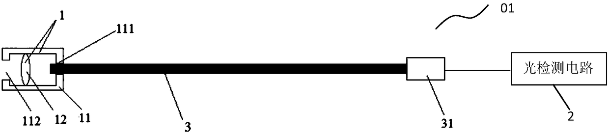
[0033] see Figure 1-Figure 3 , the present invention provides a light intensity testing device 01 capable of withstanding high electromagnetic radiation fields, including an optical probe 1 and an optical detection circuit 2, wherein the optical detection circuit 2 is connected to the optical probe 1 through an optical fiber 3 .

[0034] figure 1 It is a schematic diagram of the connection of the optical probe, the optical fiber, and the optical detection circuit provided by the embodiment of the present invention.

[0035] Such as figure 1 As shown, the optical probe 1 provided by the present invention includes a non-metallic mounting shell 11, a focusing lens 12 accommodated in the non-metallic mounting shell 11, a mounting hole 111 arranged at one end of the non-metallic mounting shell 11, and a set The light inlet hole 112 at the other end of the non-metallic mo...

Embodiment 2

[0050] Embodiment 2 A light intensity test system that can withstand high electromagnetic radiation fields 02

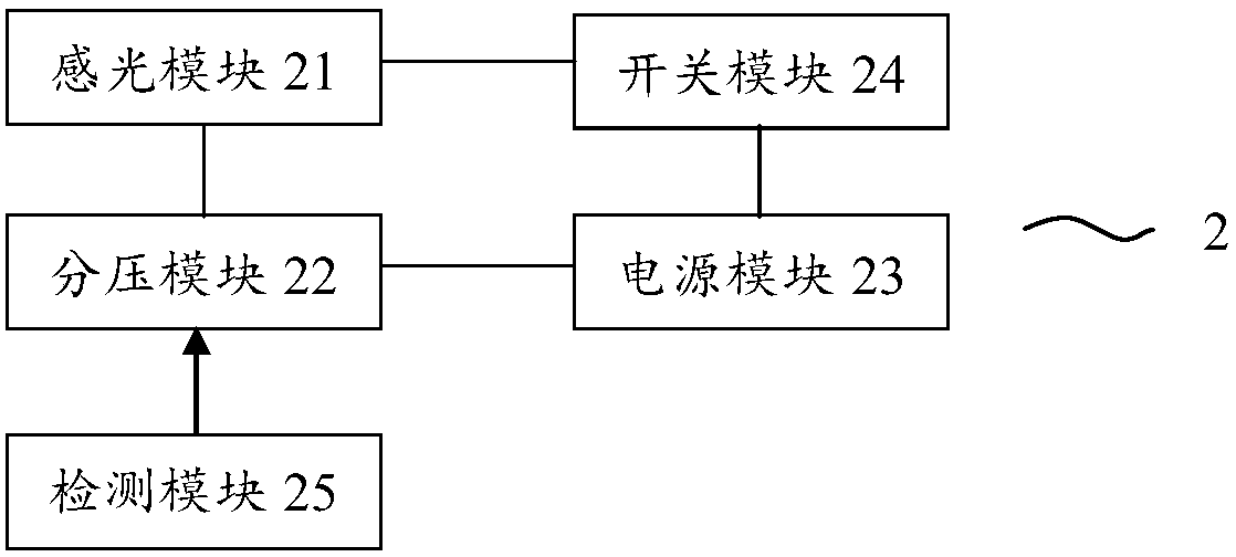
[0051] Figure 4 It is a structural schematic diagram of a light intensity test system that can withstand a high electromagnetic radiation field provided by an embodiment of the present invention. see Figure 4 , the present invention also provides a light intensity test system 02 that can withstand high electromagnetic radiation fields. The light intensity test device 01 that can withstand high electromagnetic radiation fields provided by the present invention is applied, and also includes a data acquisition card 021, and the described The upper computer 022 that the data acquisition card 021 connects; The data acquisition card 021 is used to collect the electrical signal from the test module 25, and the electrical signal is transmitted to the upper computer 022; The upper computer 022 is used to receive data from the data acquisition card 021 electrical signal, a...

Embodiment 3

[0054] Embodiment 3 application embodiment

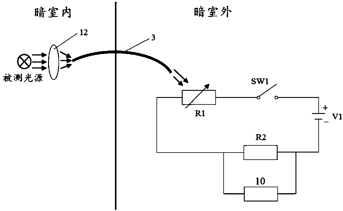
[0055] In the first application scenario of the present invention, the light intensity test device 01 that can withstand high electromagnetic radiation fields provided by the present invention or the light intensity test system 02 that can withstand high electromagnetic radiation fields are used to perform radiation immunity to the LED headlights of the car to be tested Degree test, test schematic diagram see Figure 5 .

[0056] Specifically include: place the vehicle in accordance with the provisions of the ISO11451-2 standard, place the light probe 1 directly in front of the optical center of the LED headlight of the car to be tested, and near the same height as the optical center of the car light, and guide the light to the electric wave through the optical fiber 3 Outside the dark room, measure and obtain the voltage change frequency or voltage value of the voltage dividing resistor R2 in the light detection circuit 2 under th...


PUM


Abstract

The invention provides a light intensity testing device, system and application thereof which can withstand high electromagnetic radiation field. The light intensity testing device that can withstand high electromagnetic radiation field provided by the present invention includes an optical probe and a light detection circuit, and the light detection circuit includes a photosensitive module, a voltage divider module, a power supply module, a switch module and a test module, wherein the photosensitive module, The voltage divider module, the power supply module and the switch module are connected in series to form a circuit; the test module is connected in parallel at both ends of the voltage divider module; the photosensitive module of the light detection circuit is connected to the optical probe through an optical fiber. The light intensity test device and system provided by the present invention that can withstand high electromagnetic radiation fields can directly output voltage detection values, which is convenient for testers to monitor and record. The strong test device can easily capture the measurable light and has high sensitivity.

Description

technical field [0001] The invention relates to the field of EMC compatibility testing, in particular to a light intensity testing device, system and application thereof capable of withstanding high electromagnetic radiation fields. Background technique [0002] With the widespread application of LED lights in automobiles, it has developed towards the direction of electronics, electric control and electric integration. Each electronic device and electronic control system must adapt to each other without affecting the performance of the vehicle's electromagnetic compatibility (EMC). On the other hand, it must have a certain degree of immunity to work reliably. Therefore, the EMC performance of automobile headlights has affected the safety and reliability of the vehicle and has become an important safety indicator. Traditional filament lamps are purely resistive loads. They are used under DC low voltage, have no disturbance, and have strong immunity, so there is no EMC proble...

Claims


Application Information

Patent Timeline
Patent Type & Authority Patents(China)
IPC IPC(8): G01J1/44G01R31/00
CPCG01J1/44G01R31/001
Inventor 李楠李军
Owner GUANGZHOU CHANGEN ELECTRONICS TECH CO LTD
Why Eureka
Try Eureka