
A high-speed lubrication performance testing machine for pre-repairing friction pairs and its application

A lubrication performance and friction pair technology, applied in the field of high-speed lubrication performance testing machines, can solve the problems of difficulty in meeting high-speed friction test requirements, affecting test accuracy and accuracy, and harsh conditions in the running-in process, so as to achieve high-speed lubrication performance testing, Ensure the relative motion accuracy and reduce the effect of the running-in process

Active Publication Date: 2018-08-10
HUAQIAO UNIVERSITY
View PDF6 Cites 1 Cited by
  • Summary
  • Abstract
  • Description
  • Claims
  • Application Information

AI Technical Summary

Problems solved by technology

The existing test methods for high-speed friction have the following problems: ①The conditions for the friction pair to achieve the running-in process in the high-speed process are relatively harsh, and even the stable wear stage does not appear, and the severe wear stage is directly reached; ②The grinding tool wears seriously during the high-speed friction process , even after reaching the stable wear stage, the geometry of the grinding tool has changed significantly, which affects the accuracy and accuracy of the test; ③The huge inertial force generated by the high-speed rotation in high-speed friction seriously affects the accuracy of the friction test
Due to the limitations of the above problems, the maximum speed level of the existing commercial friction and wear testing machine is about 5000rpm (friction disc with a diameter of 50mm), and the linear speed is about 7.87m / s, which is difficult to meet the test requirements of high-speed friction

Method used


Image

  • A high-speed lubrication performance testing machine for pre-repairing friction pairs and its application
  • A high-speed lubrication performance testing machine for pre-repairing friction pairs and its application
  • A high-speed lubrication performance testing machine for pre-repairing friction pairs and its application

Examples


Embodiment 1

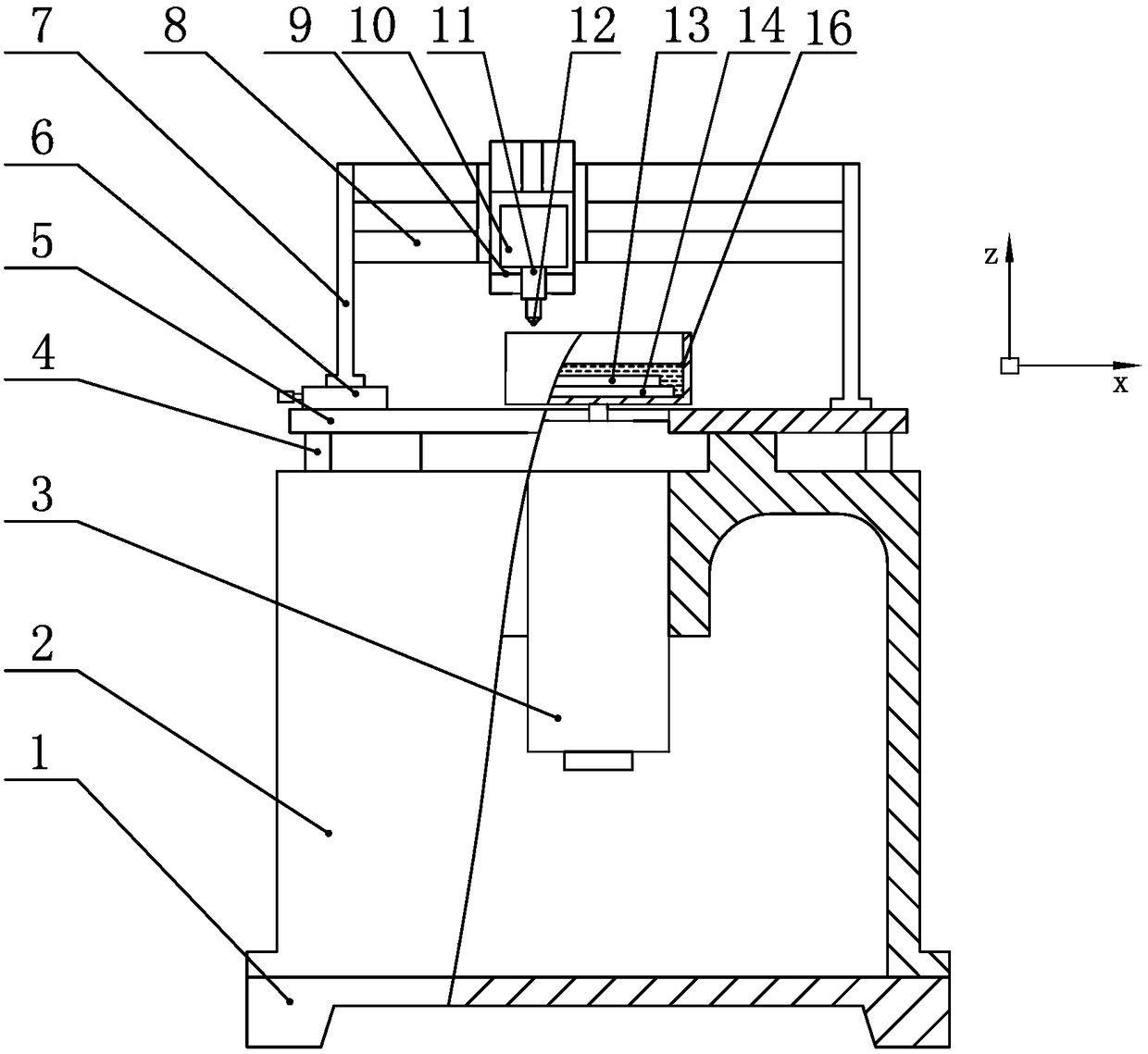
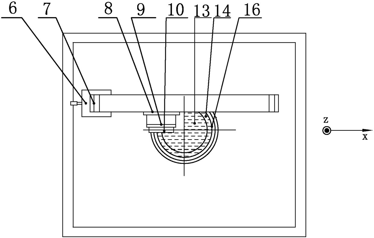
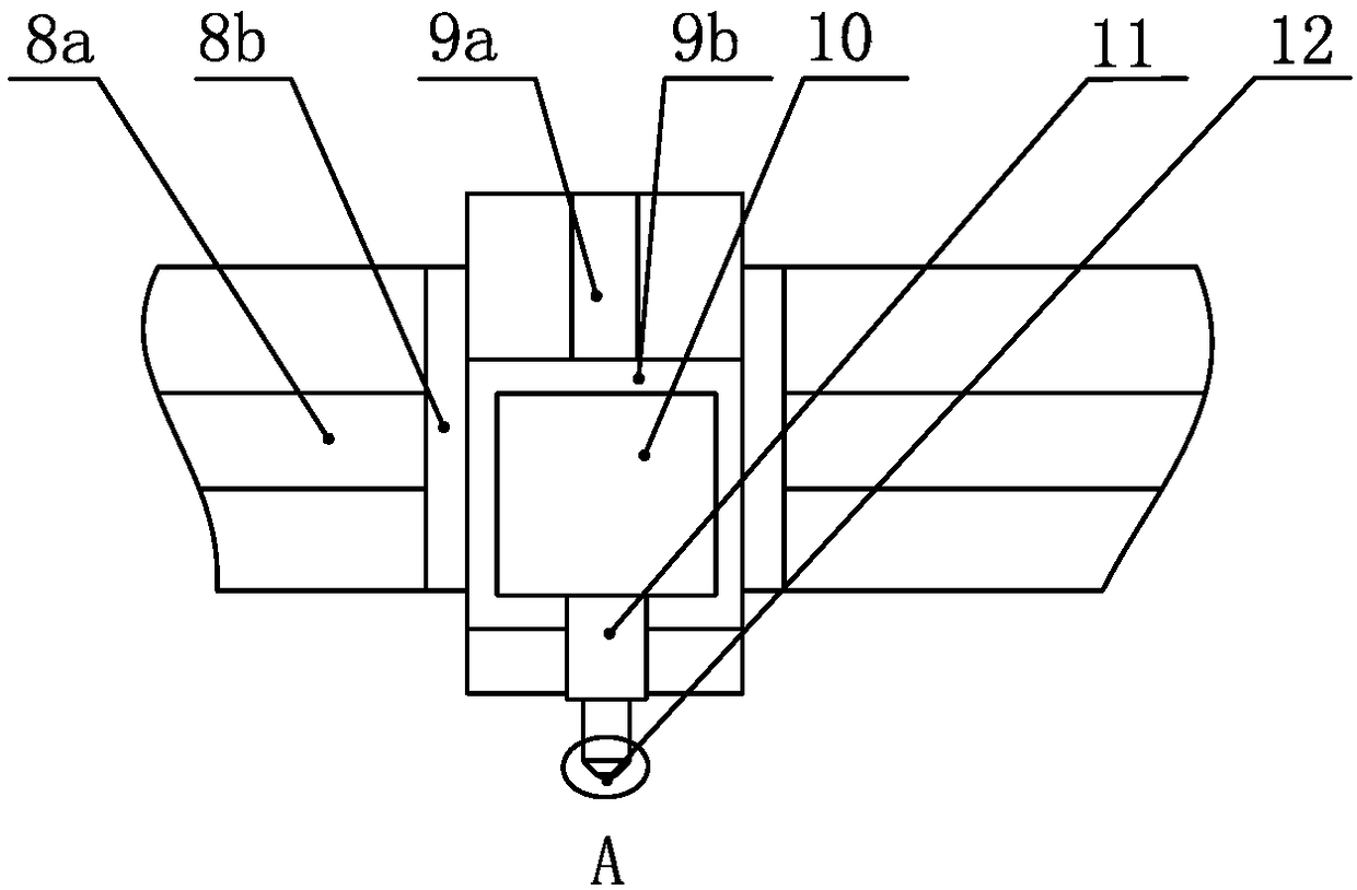
[0060] Please check Figure 1 to Figure 5 , a high-speed lubrication performance testing machine for pre-repairing friction pairs, including:

[0061] The fixed seat includes the bed 2 and the base 1 arranged up and down and fixed with bolts; the bed 2 is a cast iron structure, which can ensure the overall rigidity of the testing machine and has a certain vibration absorption capacity;

[0062] The horizontally arranged workbench 5 is fixed on the top of the bed 2; an adjustment device is provided between the workbench 5 and the bed 2, which is an adjustment screw 4 for leveling the workbench 5 and exerting a certain force on the workbench 5. Supporting function to increase the rigidity of the workbench 5; the middle part of the workbench 5 is a hole structure;

[0063] The vertically arranged electric spindle 3 is fixed on the bed 2, and the electric spindle 3 penetrates the worktable 5 upwards from the hole structure of the worktable 5; The speed change device drives the m...

Embodiment 2

[0084] Utilize the high-speed lubrication performance testing machine of the pre-repaired friction pair of the embodiment of the present invention 1 to carry out concrete test:

[0085] 1) Fix an oxygen-free copper disc-shaped friction disc 13 with a diameter of 400 mm in the center of the bottom of the splash-proof box 16, and the splash-proof box 16 is fixed on the electric spindle 3, and the friction disc 13 can be rotated by the electric spindle 3; use a dynamic balancer The friction disc 13 and the anti-splash box 16 are dynamically balanced on-line as a whole to reduce the vibration of the friction disc 13 and the anti-splash box 16 during high-speed rotation, thereby ensuring that the grinding tool 12 and the friction disc 13 can be stably touch;

[0086] 2) The electric spindle 3 drives the friction disc 13 to rotate, and the disc repair tool 15b is a diamond turning tool, which is driven by the Z-direction linear motor 9 with a certain depth of cut and driven by the X...

Embodiment 3

[0093] 1) Fix the disc-shaped friction disc 13 of gear steel 42CrMoV (hardness HRC50) with a diameter of 400mm in the center of the inner bottom of the splash-proof box 16, and the splash-proof box 16 is fixed on the electric spindle 3, and the friction disc 13 can be rotated by the electric spindle 3; Use a dynamic balancer to carry out overall online dynamic balance on the friction disc 13 and the anti-splash box 16 to reduce the vibration of the friction disc 13 and the anti-splash box 16 during high-speed rotation, so as to ensure the grinding tool 12 and the friction disc during the scratching process 13 can be stably contacted;

[0094] 2) The electric spindle 3 drives the friction disc 13 to rotate, and the disc repairing tool 15b is a CBN (cubic boron nitride) turning tool, driven by the Z-direction linear motor 9 with a certain depth of cut and driven by the X-direction linear motor 8 along the friction disc. 13 radial feed, cutting into the friction disc 13 radially ...


PUM

PropertyMeasurementUnit
diameteraaaaaaaaaa
diameteraaaaaaaaaa

Abstract

The invention discloses a high-speed lubricating performance testing machine for pre-grinding a friction pair and application thereof.The high-speed lubricating performance testing machine mainly comprises a fixing base, a workbench, an electric spindle, an anti-splashing box, a friction disk, an X-direction feeding device, a Z-direction feeding device, a clamping device, an opposite-grinding tool, a disk grinding device, a measurement system, a cutter alignment instrument and the like.After the surface of the friction disk is ground through the disk grinding device, the electric spindle drives the friction disk to rotate; after the surface of the friction disk is ground through the disk grinding device, a proper quantity of lubricating agent is placed in the anti-splashing box, the electric spindle drives the friction disk to rotate, the Z-direction feeding device and the X-direction feeding device drive the opposite-grinding tool and the friction disk to make contact with each other for friction testing, pressure between the opposite-grinding tool and the friction disk is kept constant in the testing process, and the testing system acquires data in the process.By means of the high-speed lubricating performance testing machine, high-speed friction testing stability and accuracy can be effectively improved.

Description

technical field [0001] The invention belongs to the field of tribological testing and precision and ultra-precision machining, and in particular relates to a high-speed lubricating performance testing machine for pre-repairing friction pairs and its application. Background technique [0002] Friction and wear occur in high-speed rotating machinery, material cutting and reciprocating motion, etc. The friction coefficient and wear history are of great significance for the selection of parts materials, structural design, and cooling and lubrication methods. Among them, high-speed friction and wear have different characteristics from general friction and wear: ① The inertial force generated by high-speed (line speed greater than 15m / s) will affect the adhesion of lubricating oil, and the lubricating oil will be squeezed out or thrown out from the friction area, causing friction The coefficient increases; ②High-speed friction is accompanied by severe plastic deformation of the ac...

Claims


Application Information

Patent Timeline
Patent Type & Authority Patents(China)
IPC IPC(8): G01N19/02
CPCG01N19/02
Inventor 姜峰张涛言兰徐西鹏
Owner HUAQIAO UNIVERSITY
Learn More