
Construction equipment and application of reinforced skeleton of tunnel second lining

A steel skeleton and tunnel technology, applied in tunnel lining, tunnel, shaft equipment, etc., can solve the problems of labor-intensive manual lifting, time-consuming, and limited operating space, so as to achieve sufficient and safe operating space, reduce construction costs, and improve work efficiency Effect

Active Publication Date: 2018-01-19
THE FIRST ENG CO LTD OF CTCE GRP
View PDF12 Cites 0 Cited by
  • Summary
  • Abstract
  • Description
  • Claims
  • Application Information

AI Technical Summary

Problems solved by technology

[0003] First, during the installation of steel bars, due to the failure of effective positioning of the steel bars, there may be displacement during the binding process, and there may be unevenness after the binding is completed, making it difficult to effectively control the construction quality;
[0004] Second, because the steel bars cannot be pre-positioned, the lifting of the steel bars cannot be completed mechanized at one time, and manual lifting is time-consuming and laborious during the operation;
[0005] The third is that the operating space provided by the trolley is extremely limited, and there are dead corners where the operation is difficult during construction operations, which brings potential safety hazards;
[0006] Fourth, the hanging cloth is completed manually during the construction process, which is difficult and time-consuming;
[0007] For the construction of cable troughs in tunnels, the current common method is to use bamboo plywood and steel molds for manual production and installation on site. After the concrete pouring is completed, the formwork is dismantled in a disassembled manner. This method of disassembly and assembly is labor-intensive and time-consuming. , and it is easy to cause damage to the corners during the demoulding process, affecting the appearance

Method used


Image

  • Construction equipment and application of reinforced skeleton of tunnel second lining
  • Construction equipment and application of reinforced skeleton of tunnel second lining
  • Construction equipment and application of reinforced skeleton of tunnel second lining

Examples


Embodiment Construction

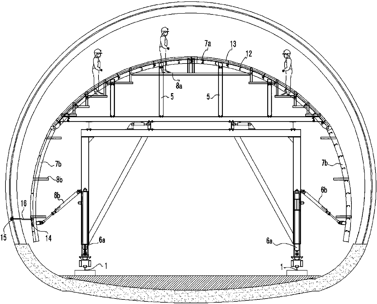
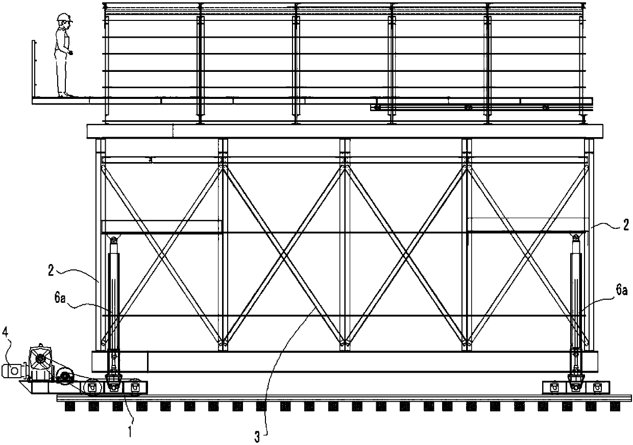
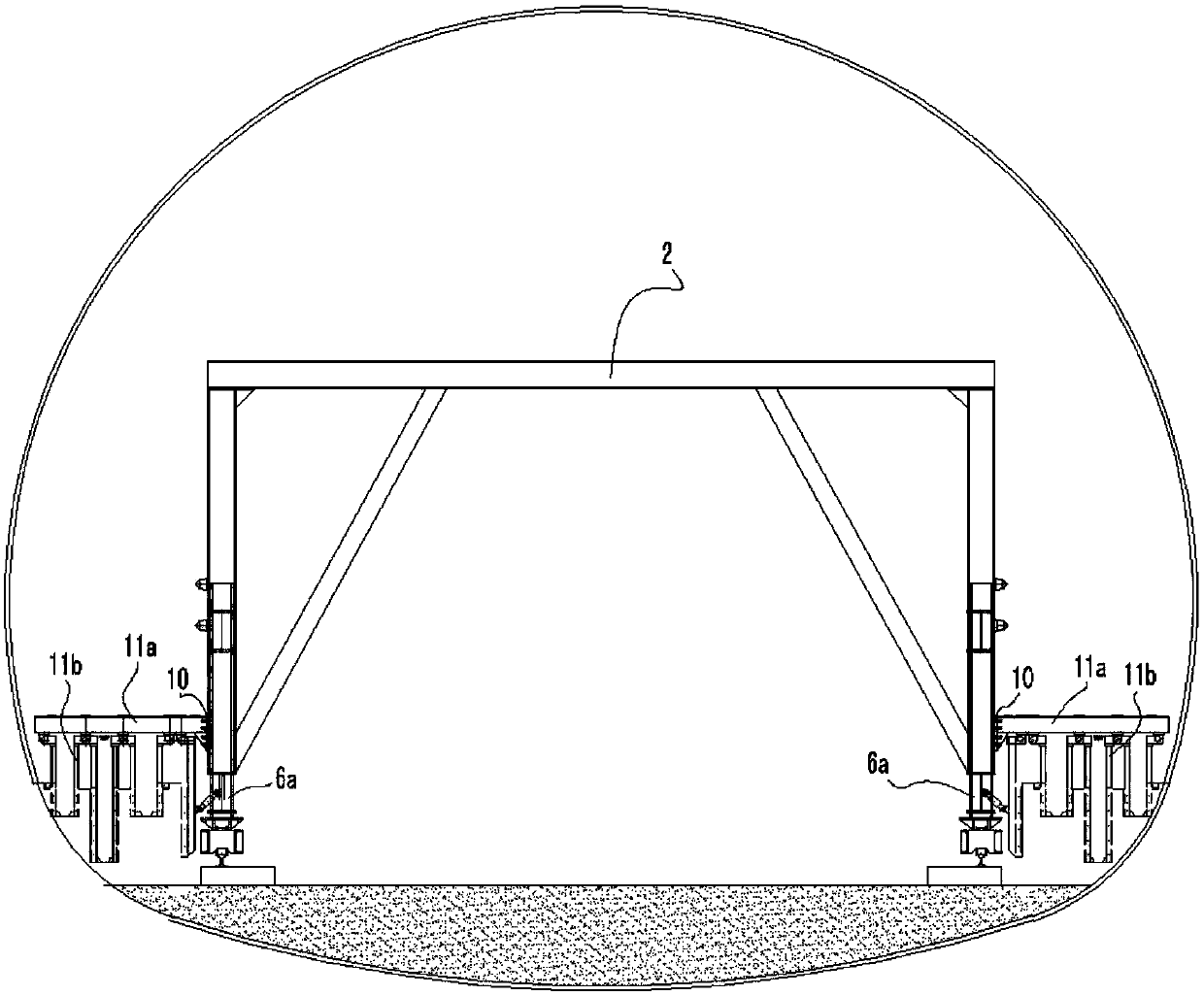
[0044] see figure 1 , figure 2 and image 3 , the structural form of the construction equipment for the second lining of the tunnel reinforced skeleton in this embodiment is:

[0045] The trolley track 1 is set to be two parallel steel rails that are auxiliary arranged in the tunnel along the direction of the tunnel.

[0046]The setting platform frame is composed of two front and rear "door" steel frames 2 and a "door" shaped truss 3 arranged between the front and rear two "door" steel frames 2; the "door" steel frame 2 and the "door" The "type trusses 3 are respectively composed of steel frame top beams and columns on both sides, and the trolley frame is supported on the trolley track 2 by using the casters at the bottom of the columns on both sides of the two "door" steel frames 2 at the front and rear, and Driven by the motor 4, it can move along the trolley track 1 to realize mechanized movement and improve construction efficiency.

[0047] At the bottom of the column...


PUM


Abstract

The invention discloses a tunnel secondary lining steel bar framework construction equipment and an application thereof. The tunnel secondary lining steel bar framework construction equipment is characterized in that a trolley rail is paved along the orientation of a tunnel; a trolley frame consisting of a portal steel frame and a portal truss can move along the trolley rail under the driving of a motor; an arched steel frame is composed by hinging arch crown frames and side arch frames arranged in section, and are supported by the trolley support. According to the tunnel secondary lining steel bar framework construction equipment, the arched steel frame can be utilized to form a steel bar framework locating jig, an operating platform can be arranged by taking the arched steel frame as a support, and further, cable duct mould bases can be installed at two sides of the portal steel frame, such that the construction equipment takes the installation of cable duct mould plates, as well as integrated construction of bar arrangement, binding, installation and hanging cloth pavement of a tunnel secondary lining steel bar framework and pavement of cable ducts into consideration to provide a safe and reliable working platform for procedure operations, therefore the engineering quality is improved, the potential safety hazards are reduced and the construction cost is reduced.

Description

technical field [0001] The invention relates to the construction equipment of the reinforced skeleton of the second lining of the tunnel, more specifically, the construction equipment applied to the installation of the reinforced skeleton in the secondary lining of the tunnel and the laying of hanging cloth. Background technique [0002] In the installation of steel frame binding and hanging cloth laying construction for the secondary lining of tunnels, the traditional method is to use steel welded steel frames to make construction trolleys, and perform manual binding and installation of hanging cloths and steel skeletons on the trolleys. The method mainly has the following problems: [0003] First, during the installation of steel bars, due to the failure of effective positioning of the steel bars, there may be displacement during the binding process, and there may be unevenness after the binding is completed, making it difficult to effectively control the construction qual...

Claims


Application Information

Patent Timeline
Patent Type & Authority Patents(China)
IPC IPC(8): E21D11/10
CPCE21D11/105E21D11/107
Inventor 蒋皓王伟李洪庆李建华赵自静祁军阮仁义梁超
Owner THE FIRST ENG CO LTD OF CTCE GRP
Learn More