
Device, method and system for positioning cerebral-cortex functional area

A technology of cerebral cortex and functional areas, applied in the field of neurosurgery, can solve problems such as short experiment time, small amount of calculation, and complex algorithms, and achieve the effects of overcoming the lag of response signals, improving accuracy, and realizing synchronization

Active Publication Date: 2016-06-15
TSINGHUA UNIV
View PDF6 Cites 9 Cited by
  • Summary
  • Abstract
  • Description
  • Claims
  • Application Information

AI Technical Summary

Problems solved by technology

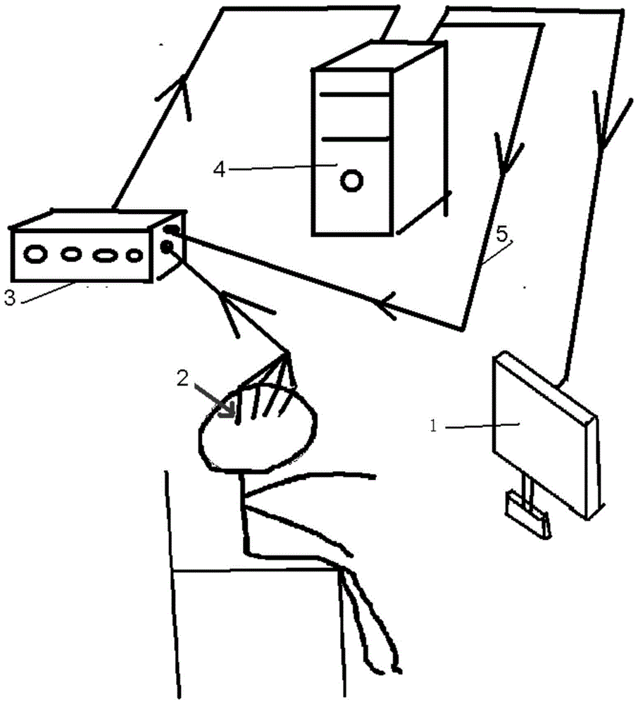
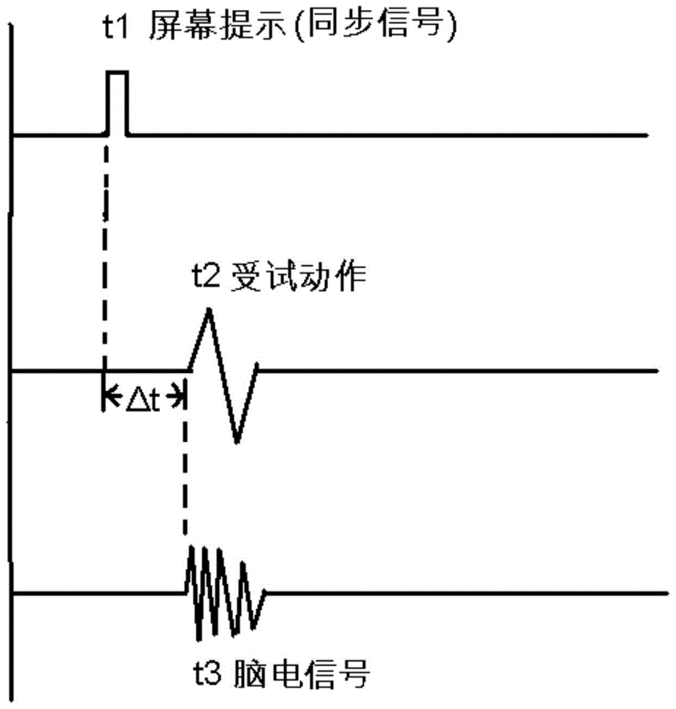
[0021] For this reason, the first technical problem to be solved by the present invention is that the signal synchronization method in the prior art cannot achieve real synchronization, and there are synchronization errors, which affect the accuracy of subsequent processing, thereby proposing a method that can well realize signal synchronization. Cerebral cortex functional area positioning device, method and system
[0022] Another technical problem to be solved by the present invention is that the power spectrum modeling method of high-frequency intracranial EEG in the prior art has the disadvantages of complex algorithm and long experiment time, so a brain brain with a small amount of calculation and short experiment time is proposed. Method and device for locating cortical functional area

Method used


Image

  • Device, method and system for positioning cerebral-cortex functional area
  • Device, method and system for positioning cerebral-cortex functional area
  • Device, method and system for positioning cerebral-cortex functional area

Examples


Embodiment 1

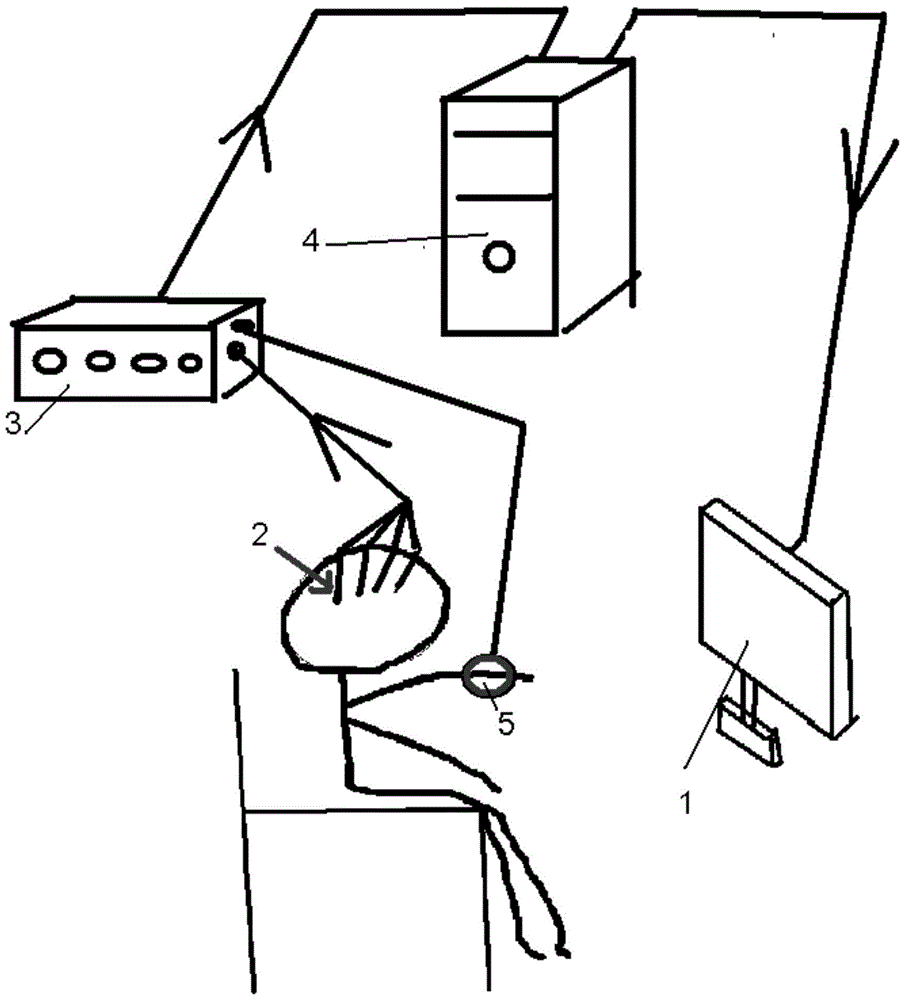
[0076] A device for positioning cerebral cortex functional areas is provided in this embodiment, such as image 3 As shown, it includes prompt screen 1, intracranial electrode 2, EEG amplifier 3, computer 4, and myoelectric electrode 5. in,

[0077] One myoelectric electrode 5 is set on the wrist of the subject to obtain the myoelectric signals of fingers, palms, wrists and other parts, so as to obtain the starting moment of the body movement.

[0078] In other alternative embodiments, a plurality of myoelectric electrodes can also be set, which are respectively placed on multiple moving parts of the subject to collect the myoelectric signals of the set parts, such as footsteps, legs, face and other positions.

[0079] There are one or more intracranial electrodes 2, which are respectively set at different positions under the cerebral cortex of the subject, and the intracranial EEG signals of the cerebral cortex at the set position are collected for subsequent judgment of whe...

Embodiment 2

[0085] In this embodiment, a method for locating functional regions of the cerebral cortex is provided, which can be used in the computer in Embodiment 1 and realized by operating instructions with the following functions. Including the following steps, the flow chart is as follows Figure 4 As shown,:

[0086]S1. First, obtain the original intracranial EEG signal and the original EMG signal of the moving part, which can be obtained by the EEG amplifier 3 in Embodiment 1. Using the device in Example 1, the original myoelectric signal can be obtained by the myoelectric electrode 5 arranged at the moving part, and the original intracranial EEG signal can be obtained by the intracranial electrode 2, and then the EEG signal and the EEG signal can be obtained by the EEG amplifier 3 The EMG signals are sent to the computer together.

[0087] S2. Then, separately process the original intracranial EEG signal and the original EMG signal.

[0088] S2-1. For the original electromyogra...

Embodiment 3

[0124] Also provide a kind of cerebral cortex functional region positioning system in the present embodiment, be used in the computer in embodiment 1, comprise:

[0125] Signal acquisition unit: respectively acquire the original intracranial EEG signal and the original EMG signal of the moving part;

[0126] The starting moment acquisition unit: acquire the starting moment of the body movement according to the original myoelectric signal;

[0127] Argument matrix acquisition unit: acquire the argument matrix of the myoelectric signal after the initial moment;

[0128] The intracranial EEG signal acquisition unit: intercepting the intracranial EEG signal of the corresponding time period according to the starting moment of the body movement;

[0129] A response variable matrix acquisition unit: acquire a response variable matrix according to the intracranial EEG signal;

[0130] Correlation calculation unit: calculate the correlation between the independent variable matrix and...


PUM


Abstract

The invention provides a device for positioning a cerebral-cortex functional area. The device comprises a reminding screen and an intracranial electrode, and further comprises one or more electromyographic electrodes arranged at movement parts of a subject, electromyographic signals are collected and used for allowing moments of action performing of the subject and staring moments of intracranial brain-electrical signal observing of the subject to be synchronous. The invention further provides a method for positioning the cerebral-cortex functional area. The method includes the steps that starting moments of human-body actions are obtained according to original electromyographic signals, then intracranial brain-electrical signals in the corresponding time periods are obtained, and synchronization of the intracranial brain-electrical signals and human-body signals is achieved; then response variable matrixes are generated according to the intracranial brain-electrical signals, independent variable matrixes are generated according to the human-body signals, and the cerebral-cortex area corresponding to the human-body actions is determined by calculating the correlation between the independent variable matrixes and the response variable matrixes. By means of the technical scheme, synchronization between the human-body actions and the intracranial brain-electrical signals can be well achieved, and the accuracy of follow-up processing can be improved.

Description

technical field [0001] The present invention relates to the field of neurosurgery. Specifically, it is a device, method and system for locating functional areas of the cerebral cortex. Background technique [0002] Clinically, before neurosurgery, in order to ensure the effect of surgery, a full and rigorous preoperative evaluation is required. Previous studies have shown that different areas of the cerebral cortex correspond to different functions of the human body, such as motor areas, language areas, visual areas, and so on. In neurosurgery, on the one hand, it is necessary to remove the lesion areas on the cerebral cortex that cause neurological diseases, and on the other hand, these normal functional areas of the patient should be preserved as much as possible to minimize the loss of the patient's normal human body functions. To achieve this goal, it is necessary to accurately locate the main functional areas of the cerebral cortex during preoperative assessment, so a...

Claims


Application Information

Patent Timeline
IPC IPC(8): A61B90/10A61B5/0476A61B5/0488
CPCA61B5/369A61B5/389
Inventor 洪波钱天翼何永振
Owner TSINGHUA UNIV
Learn More