
A Fixed Bed Multiphase Atomizing Nozzle

An atomizing nozzle and fixed bed technology, applied in the field of fixed beds, can solve the problems of limited atomization range on the bed surface, uneven liquid phase pipeline size, easy deformation of threads, etc., so as to increase the atomization range and uniformity. The effect of increasing the atomization angle and mixing range, and prolonging the service life

Active Publication Date: 2018-03-30
CHNA ENERGY INVESTMENT CORP LTD +2
View PDF10 Cites 0 Cited by
  • Summary
  • Abstract
  • Description
  • Claims
  • Application Information

AI Technical Summary

Problems solved by technology

[0005] The traditional atomizing nozzles for fixed beds have the following defects: firstly, the gas phase channel of the traditional atomizing nozzles is formed by the annular gap between the liquid phase nozzle and the gas phase nozzle, and this annular gap is in the form of "shrinking" In this structure, the extrusion effect of gas phase flow on liquid phase flow is very obvious, especially in the case of high load gas-liquid ratio, the atomization angle is even less than 15°, and the liquid phase distribution presents a state of high in the middle and low on both sides , so that the atomization range formed on the surface of the bed is very limited, even less than 1 / 3 of the required coverage, and the atomization uniformity is poor
In addition, since there are solid impurities of uneven size in the liquid phase pipeline in the MTP reaction system, it is very easy to cause blockage and wear problems
In addition, since the feed temperature of the liquid phase material is between 35°C and 75°C, the feed temperature of the gas phase material is between 200°C and 280°C, and the local maximum temperature of the bed can reach 500°C to 550°C, so in the above atomizing nozzle, The temperature difference between the inside and outside of the liquid phase nozzle changes greatly, so the thread connection between the liquid phase nozzle and the mounting end seat is prone to deformation and seizure due to thermal stress

Method used


Image

  • A Fixed Bed Multiphase Atomizing Nozzle
  • A Fixed Bed Multiphase Atomizing Nozzle
  • A Fixed Bed Multiphase Atomizing Nozzle

Examples


Embodiment 1

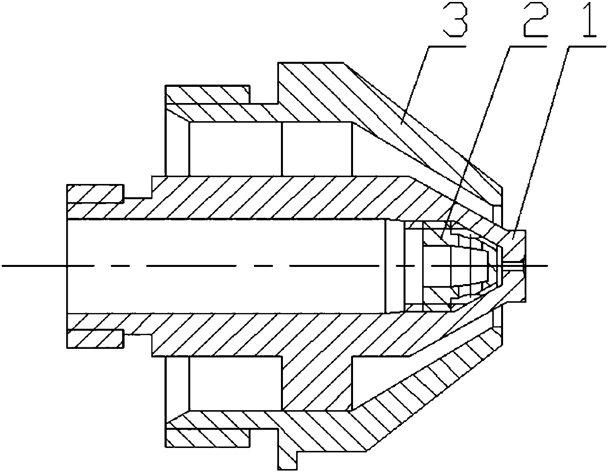
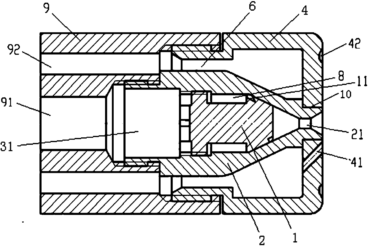
[0070] A fixed bed multiphase atomizing nozzle, such as figure 2 , 8 -shown in 14 and 17, including swirler 1, inner nozzle 2, outer nozzle 4 and installation end seat 9; said installation end seat 9, swirler 1, inner nozzle 2 and outer nozzle 4 are coaxially arranged; all The cyclone 1 is set in the inner nozzle 2 , and the inner nozzle 2 is set in the outer nozzle 4 .

[0071] The head 111 of the swirler 1 is provided with a plurality of first swirl grooves 11;

[0072] The outer wall of the cyclone 1 and the inner wall of the inner nozzle 2 define a liquid phase channel 8;

[0073] The head of the inner nozzle 2 is provided with a liquid phase spray hole 21;

[0074] The liquid phase channel 8 is communicated with the liquid phase nozzle hole 21 through the plurality of first swirl grooves 11;

[0075] The middle part of the head end face of described outer nozzle 4 is provided with the fixing hole 10 that is used to fix described inner nozzle 2 head; The outer wall of...

Embodiment 2

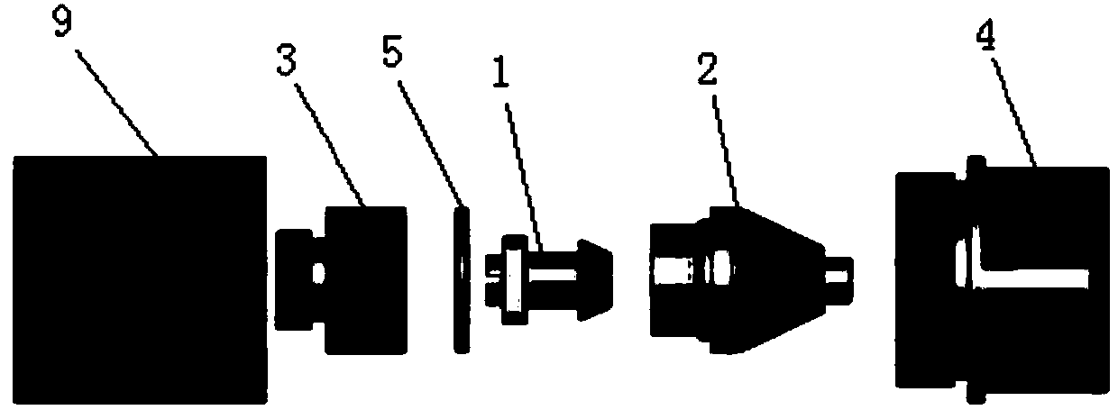
[0090] A fixed bed multiphase atomizing nozzle, such as Figure 3-17 As shown, including the cyclone 1, the inner nozzle 2, the outer nozzle 4, the inner connecting piece 3 and the installation end seat 9; the installation end seat 9, the inner connecting piece, the swirler 1, the inner nozzle 2 and the outer nozzle 4 are arranged coaxially; the swirler 1 is set in the inner nozzle 2, and the inner nozzle 2 is set in the outer nozzle 4.

[0091] The head 111 of the swirler 1 is provided with a plurality of first swirl grooves 11;

[0092] The outer wall of the cyclone 1 and the inner wall of the inner nozzle 2 define a liquid phase channel 8;

[0093] The head of the inner nozzle 2 is provided with a liquid phase spray hole 21;

[0094] The liquid phase channel 8 is communicated with the liquid phase nozzle hole 21 through the plurality of first swirl grooves 11;

[0095] The middle part of the head end face of the outer nozzle 4 is provided with a fixing hole 10 for fixing...

Embodiment approach

[0112] In all the above embodiments, the angle of the swirl hole 41 can be changed through a punching machine according to the needs of the actual atomization process. The implementation method of this kind of swirl hole is briefly described as follows: first determine the oblique tangential angle and hole distance of the holes, and then implement tangential perforation on the outer nozzle along the determined angle and hole distance through piercing machines of different sizes. like Figure 7 As shown in the structural diagram of the outer nozzle, the 5 oblique tangential swirl holes 41 on the outer nozzle have the same angle and direction. If it needs to be changed, it can be realized by the above-mentioned implementation method, which is "variable tangential angle". .

[0113] In all the above embodiments, the cyclone 1 is made of wear-resistant materials.

[0114] The wear-resistant material is preferably nickel-based alloy 718.

[0115] Comparing the atomizing nozzle o...


PUM


Abstract

The invention provides a fixed bed multiphase atomizing nozzle, comprising a whirlcone, an inner nozzle and an outer nozzle which are coaxially arranged in sequence; the head of the whirlcone is provided with multiple first whirling grooves; the outer wall of the whirlcone and the inner wall of the inner nozzle define a liquid phase channel; the head of the inner nozzle is provided with a liquid phase spray orifice; the liquid phase channel is communicated with the liquid phase spray orifice by the first whirling grooves; the area of the end face of the head of the outer nozzle is 1.5-5 times the cross sectional area of the greatest cross section of the inner nozzle; the middle of the end face of the head of the outer nozzle is provided with a fixing hole; the outer wall of the inner nozzle and the inner wall of the outer nozzle define a gas phase channel; the end face of the head of the outer nozzle is provided with multiple whirling holes around the fixing hole, and the gas phase channel is communicated with the whirling holes; on the end face of the head of the outer nozzle, the outer sides of the whirling holes are further provided with multiple gas phase spray holes around the fixing hole, and the multiple gas phase spray holes are communicated with the gas phase channel. According to the atomizing nozzle, the atomizing angle and the atomizing diameter are both increased greatly, the atomizing effect is better, and the atomizing range is larger.

Description

technical field [0001] The invention belongs to the field of fixed beds, in particular to a fixed bed multiphase atomization nozzle. Background technique [0002] Propylene is an important basic organic raw material, mainly used in the production of derivative chemicals such as polypropylene, acrylonitrile, ethylene oxide, and acrylic acid. For a long time, propylene has mainly come from catalytic cracking in refineries and steam cracking of hydrocarbons. Facing my country’s energy pattern with more coal and less oil, it is of great practical significance to convert coal with low added value into propylene derivatives with higher added value . The methanol to propylene (Methanol to Propylene, MTP) process is a process that uses coal-based methanol as a raw material and reacts on a ZSM-5 molecular sieve catalyst to produce propylene as the target product. [0003] However, during the operation of the MTP reactor, the service life of the catalyst and the yield of propylene ar...

Claims


Application Information

Patent Timeline
Patent Type & Authority Patents(China)
IPC IPC(8): B01J8/02
CPCB01J8/0278B01J2208/00548
Inventor 庄壮匡建平罗春桃梁健雍晓静张世程魏旭礼王峰张伟江永军苏慧王亮杜正平梁吉宝
Owner CHNA ENERGY INVESTMENT CORP LTD
Learn More