
Composite-structure double-layer metal grating polarization beam splitter

A polarizing beam splitter and metal grating technology, applied in diffraction gratings, optics, instruments, etc., can solve the problems of narrow working band, limitation, and sensitivity to light incident angles, and achieve the expansion of wavelength range, ease of period and slit width. Contradictory, favorable preparation effects

Active Publication Date: 2016-06-01
SHANGHAI JIAO TONG UNIV
View PDF7 Cites 15 Cited by
  • Summary
  • Abstract
  • Description
  • Claims
  • Application Information

AI Technical Summary

Problems solved by technology

[0003] Traditional polarizing beam splitters are usually based on dichroic materials such as birefringent crystals or multilayer dielectric films. Their disadvantages are that they are sensitive to the incident angle of light and are limited by the refractive index of the actual crystal and medium. , the working band is narrow
2012 L. Wang et al. ("High performance Albi-layer wire-grid polarizer for deep-ultraviolet to infrared: modeling and design from ultraviolet to infrared light double-layer wire grid high-performance polarizer: model and design", LiWang, HarunH.Solak, and YasinEkinci, Proc.ofSPIE, 8424, 842429 (2012)) simulated and studied the transmission efficiency of TM and TE polarized light of double-layer gratings, and proved by comparison that although the TM transmittance of double-layer metal is lower than that of single-layer metal, the polarization suppression ratio exceeds that of single-layer by 1-2 magnitude
However, when the grating period is large and the slit is wide, TE polarized light will also enter the slit in the conventional waveguide mode, resulting in diffraction and transmission, reducing the polarization suppression ratio in reflection, transmission, and other diffraction directions

Method used


Image

  • Composite-structure double-layer metal grating polarization beam splitter
  • Composite-structure double-layer metal grating polarization beam splitter
  • Composite-structure double-layer metal grating polarization beam splitter

Examples


Embodiment 1

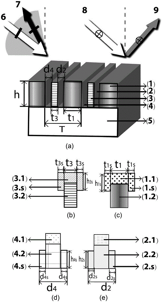
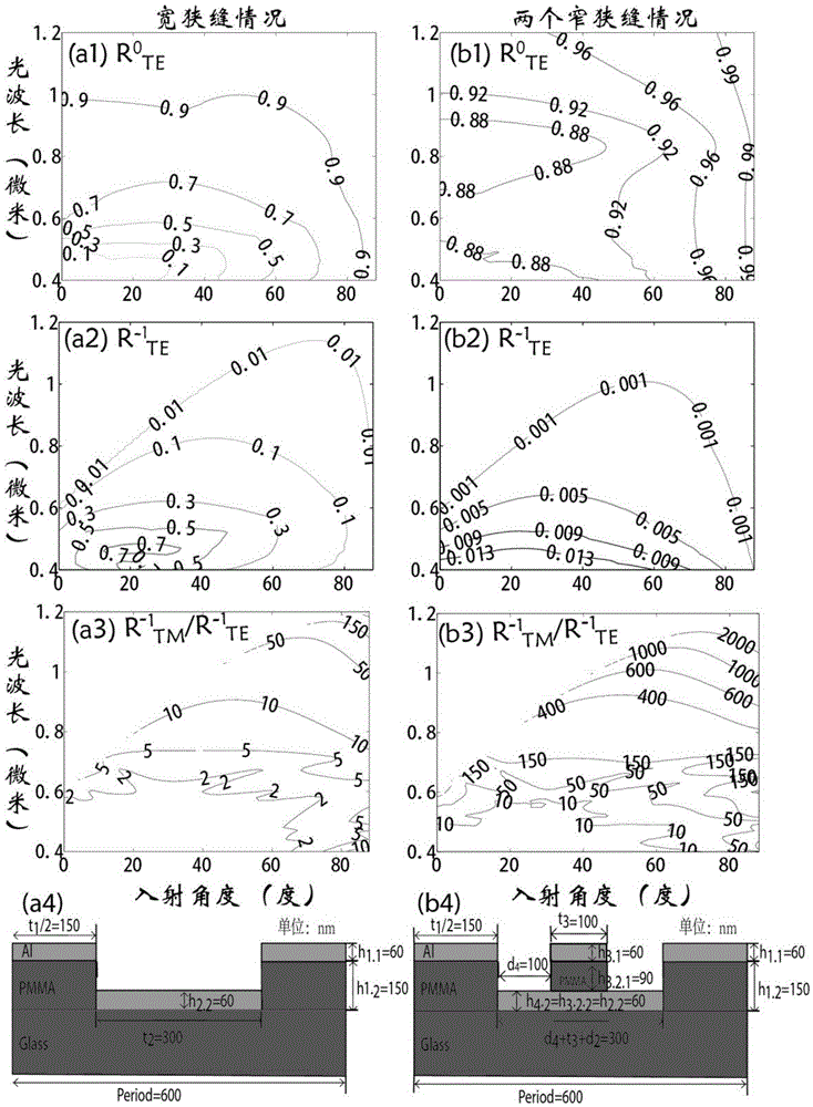
[0032] Embodiment 1: A compound structure metal grating polarization beam splitter improves the extinction ratio of back diffraction by 10-20 times. Combining the simulation results of the commercial software RSOFT and the schematic diagram of the grating structure figure 2 , and the left and right columns correspond to the case of simple and composite metal aluminum gratings, respectively. The period of the grating is 600 nanometers; the second material 2 is the same as the fourth material 4, the upper material is air with a thickness of 150 nanometers, the lower material is metal aluminum with a thickness of 60 nanometers, and the width is 100 nanometers; the first material 1 The width is half of the period, i.e. 300 nanometers, wherein the upper layer material 1.1 in the first material is an aluminum film with a thickness of 60 nanometers, and the lower layer material 1.2 in the first material is PMMA (refractive index 1.55) with a thickness of 150 nanometers; the third T...

Embodiment 2

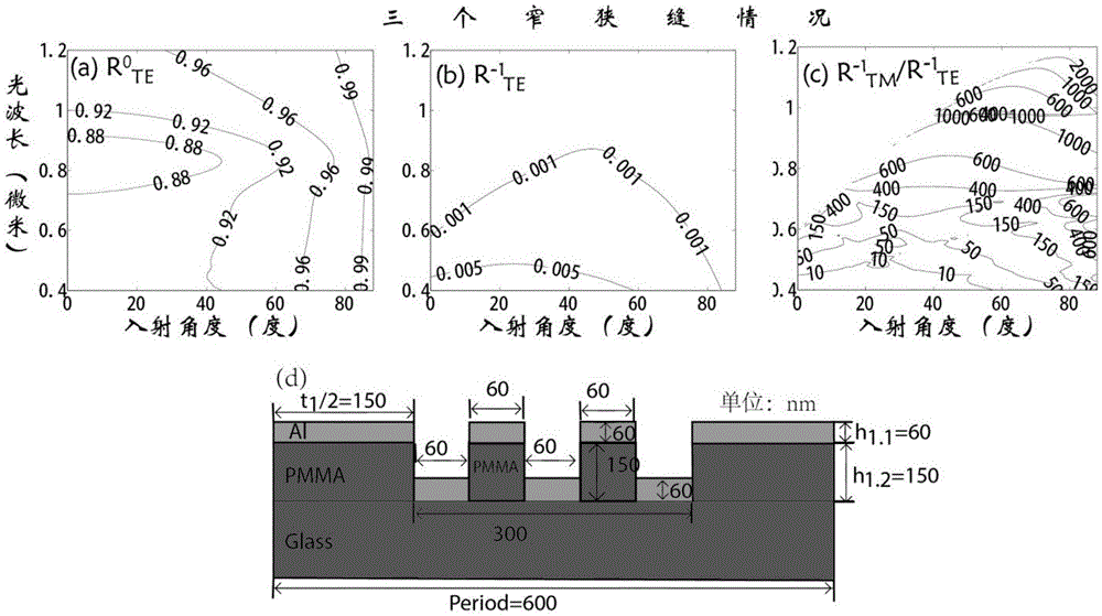
[0033] Embodiment 2: A composite structure metal grating polarization beam splitter improves the extinction ratio of back diffraction in the visible light band in a wide range of angles. Combining the simulation results of the commercial software RSOFT and the schematic diagram of the grating structure image 3, the difference between the grating structure and embodiment 1 is that there are three slits in the grating period: the three slits are all the same, the upper layer material is air with a thickness of 150 nanometers, and the lower layer material is metal aluminum with a thickness of 60 nanometers, and its width is the same. It is 60 nanometers; the first material is the same as the first material in embodiment 1; the two kinds of materials separating the three slits are the same, and the width is 60nm, and its upper layer material is all aluminum with a thickness of 60 nanometers, and the lower layer material is all aluminum with a thickness of 60 nm. 150nm PMMA. The ...

Embodiment 3

[0034] Embodiment 3: A THz band plasmonic polarization beam splitting device using a metal grating with a composite structure, such as Figure 4 As shown, four slits are included in the grating period, and the slits are all the same, the upper layer material is air with a thickness of 2.5 microns, and the lower layer material is composed of composite metal chromium-aluminum-chromium with a thickness of 1.2 microns, and its width is 4 / 7 microns; the width of the first material is 4 microns, the upper material is composed of composite metal chromium-aluminum-chromium with a thickness of 1.2 microns, and the lower material is PMMA with a thickness of 2.5 microns; the three materials for isolating the four slits are the same , with a width of 4 / 7 microns, the upper layer material is composed of composite metal chromium-aluminum-chromium with a thickness of 1.2 microns, and the lower layer material is PMMA with a thickness of 2.5 microns. The composition of the above composite met...


PUM

PropertyMeasurementUnit
Thicknessaaaaaaaaaa
Thicknessaaaaaaaaaa
Thicknessaaaaaaaaaa

Abstract

Provided is a composite-structure metal grating polarization beam splitter. Each grating period has two or more medium slits separated by a metal material; and a waveguide structure formed by the plurality of medium slits meets waveguide mode cutoff of electromagnetic waves of an incident electric field parallel to grating lines in slit waveguide, and the grating period meets existence of diffraction of incident transverse magnetic field electromagnetic waves at a certain incident angle. Through the utilization of the appropriate number of medium slits, and by enabling width of waveguide formed by the plurality of slits to be smaller than mode cutoff width of working wavelength TE polarized wave, the TE polarized wave cannot be propagated in the slits, so that the TE polarized incident waves only have reflected waves, but does not have other diffracted waves; meanwhile, by controlling the grating period, the polarization beam splitter grating is allowed to have 0-level and+ / -1-level and above reflection diffraction or transmission diffraction for the TE polarized light; and broadband, large-angle range, reflection / diffraction / transmission polarization beam splitting under a larger metal grating period can be realized.

Description

Technical field: [0001] This patent relates to the technical field of polarized beam splitting devices, especially a wide-spectrum polarized beam splitting based on a metal grating with a composite structure, using the surface plasmon waveguide cut-off effect to produce an adjustable angle, transverse electric field reflection, transverse magnetic field diffraction or transmission raster. The utility model belongs to a polarization beam splitting device in the field of optics. Background technique: [0002] Polarized light is widely used in modern optical technology and its applications, such as flat panel display and three-dimensional display, optical communication, optical storage, and optical sensing. Polarizing beam splitter is an optical device that splits incident light into two beams whose polarization directions are perpendicular to each other. It is an important component in modern optical systems. Furthermore, a large-angle, broadband polarizing beam splitter wit...

Claims


Application Information

Patent Timeline
IPC IPC(8): G02B27/28G02B5/18G02B27/42
CPCG02B5/1861G02B27/283G02B27/4261
Inventor 叶志成郑君
Owner SHANGHAI JIAO TONG UNIV
Learn More