
Operation mode and structure of a heat circulation heat pump drying device

A technology of heat pump drying and drying equipment, which is applied in the direction of drying, drying machine, and drying gas arrangement, etc., which can solve the problems of poor water removal effect, lower energy efficiency ratio of the heat pump system, and slow temperature rise of the air in the oven. Effects of improved SMER, high COP value, and shortened drying time

Active Publication Date: 2018-09-21
淄博绿爽食品有限公司
View PDF8 Cites 0 Cited by
  • Summary
  • Abstract
  • Description
  • Claims
  • Application Information

AI Technical Summary

Problems solved by technology

The disadvantage is that the temperature of the air in the oven rises very slowly, and the heat obtained by the inner cavity of the oven is only the heat converted by the energy consumed by the heat pump device. The gas temperature of the evaporator is low, the ratio of latent heat / sensible heat in the heat absorbed by the evaporator is very low, the drying and dehumidification effect is poor, and the drying speed is slow
Especially because the condenser and the evaporator share a fan, when the condensing air volume is the same as the evaporating air volume, if the latent heat absorbed by the evaporator is greater than the sensible heat, the temperature difference between the inlet and outlet air of the condenser is more than 2.5 times the temperature difference between the inlet and outlet air of the evaporator, making the condenser If the air outlet temperature of the condenser is too high, the condensation temperature of the refrigerant is too high, resulting in a decrease in the energy efficiency ratio of the heat pump system; if the latent heat absorbed by the evaporator is less than the sensible heat, although the disadvantage of too high air outlet temperature of the condenser can be avoided, the latent heat / sensible heat is less than 1, Reduce the conversion rate between latent heat and sensible heat of the air in the oven, resulting in poor dehydration effect
The overall effect is equivalent to that of Class A open devices: Class B closed heat pump drying devices can save energy by more than 50% compared with electric heating drying, and the SMER is about 2 to 2.5, and it is difficult to exceed 3, especially in winter. When the temperature is very low, the drying effect is worse

Method used


Image

  • Operation mode and structure of a heat circulation heat pump drying device
  • Operation mode and structure of a heat circulation heat pump drying device

Examples


Embodiment 1

[0032] Embodiment 1: Frequency conversion heat pump clothes dryer.

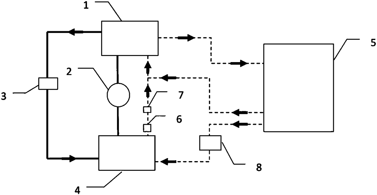
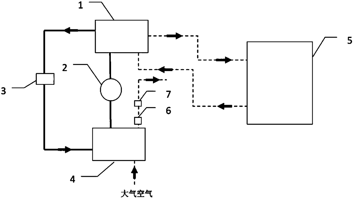
[0033] The heat pump system of this embodiment is a frequency conversion heat pump system, including a heat pump system composed of a compressor 2, a throttle valve 3, a condenser 1, an evaporator 4, a fan, etc., and an oven box, etc. An adjustable damper 8 is installed on the heat recovery air duct in the device, and an exhaust pipe 6 and an air suction pipe 7 are also included. In the initial stage of device operation, it is in the heating mode. The damper can be adjusted so that the inlet and outlet of the heat recovery air duct are connected to the atmosphere and isolated from the inner cavity of the oven. There is a fan to make the atmospheric air flow in from the inlet of the air duct and flow through it. After the evaporator is emptied into the atmosphere from the air outlet of the air duct, the heat absorbed by the evaporator is released by the condenser 1 and the condensing fan to the inner cavity of...

Embodiment 2

[0034] Embodiment 2. Drying device for dual heat pump system

[0035] The structure of this embodiment is similar to that of Embodiment 1, the difference is: A. There are two independent heat pump systems, and the evaporators of the two heat pump systems are installed in series upstream and downstream of the heat recovery air duct. B. The device is equipped with an exhaust port leading to the atmosphere with a fan and an air intake pipe leading to the atmosphere, and the exhaust port is upstream of the air intake pipe. C. A sensible heat exchanger is installed in the device.

[0036] In the initial stage of device operation, the adjustable damper is controlled so that the inlet and outlet of the heat recovery air duct are connected to the atmosphere and isolated from the inner cavity of the oven, and there is a fan to allow atmospheric air to flow in from the inlet of the air duct and flow through the evaporator Afterwards, it is emptied from the air outlet of the air duct in...


PUM


Abstract

The invention discloses operation modes and a structure of a heat-circulation heat pump drying unit. The structure is characterized in that the drying unit comprises a heat recovery air duct which forms a sealed air flow circulation loop with the inner cavity of the drying oven, an evaporator is installed in the air duct, and an air regulator for regulating and controlling the air flowing through the evaporator is arranged in the unit. The operation modes are a heating mode and a heat-circulation dehumidification mode. In the early operation stage of the unit, the heating mode is started, the heat pump system absorbs heat from the atmosphere, so that the air in the drying oven is heated to achieve the preset temperature; and then, the unit operates the heat-circulation dehumidification mode, the high-temperature high-humidity gas in the drying oven flows through the evaporator in the air duct to be cooled and dehumidified and then flows back to the drying oven, the sensible heat and latent heat absorbed by the evaporator are released into the drying oven by a condenser, and the air regulator enables the ratio of the condensation air quantity to evaporation air quantity to be greater than 2 and controls the inlet / outlet air temperature difference of the evaporator to be 10-25 DEG C. The unit has the advantages of high average COP and high latent heat ratio in the heat absorbed by the evaporator; and the dehydrating amount per kilowatt-hour is 5 kilograms or above, so that the efficiency is enhanced by 70-130% as compared with the conventional heat pump drying.

Description

technical field [0001] The invention discloses the operation mode and structure of a heat circulation heat pump drying device. The scope of application is: high and medium temperature heat pump drying and dehumidification. The range of drying and drying items is grain, vegetables and fruits, tobacco leaves, bacon, aquatic products, clothing fabrics, Chinese medicinal materials, wood, peat, various industrial and agricultural raw materials and products, etc. Background technique [0002] The types of material drying are extremely wide and the quantity is huge, and the energy consumption of the whole society for material drying is very huge. According to some data, the energy consumption for drying and drying materials in developed countries accounts for between 7% and 15% of the total energy consumption, with an average of 12%. Now China's annual power generation is about 5 trillion kWh. If the electricity consumption for drying is estimated to be 8% of the total power gene...

Claims


Application Information

Patent Timeline
Patent Type & Authority Patents(China)
IPC IPC(8): F26B21/00F26B21/04F26B21/10F26B21/08F26B21/12
CPCF26B21/001F26B21/002F26B21/04F26B21/086F26B21/10F26B21/12Y02P70/10
Inventor 郏松筠
Owner 淄博绿爽食品有限公司
Learn More