
left ventricular assist device

A technology of auxiliary devices and driving devices, which is applied in the field of medical devices and can solve problems such as easy formation of thrombus, large driving devices, and easy infection of target points

Active Publication Date: 2017-12-08
深圳市华畅医疗创新有限公司
View PDF8 Cites 4 Cited by
  • Summary
  • Abstract
  • Description
  • Claims
  • Application Information

AI Technical Summary

Problems solved by technology

The disadvantages of temporary left ventricular assist devices are: not suitable for long-term assistance; implanted in the neck or groin area, only suitable for bedridden patients, and need sedation during use; the target point of transvascular delivery is susceptible to infection
[0005] The pneumatic pump in the long-term left ventricular assist device has the advantages of easy replacement of consumables and simple design of the driving device. The disadvantage is that the driving device is bulky and not suitable for placement in the body. Adverse psychological effects on patients; pipelines are needed to connect the heart chamber and aorta, increasing energy consumption, and prone to thrombosis
The axial flow pump in the long-term left ventricular assist device has the advantage that the axial flow pump can be built in, but the disadvantages are: the apex of the left ventricle is perforated, which destroys the integrity of the ventricle and has a negative impact on the recovery of ventricular function; the pipeline connects the pump body and the ascending aorta ; Although the pump body has been greatly reduced, it is still located between the epicardium and the pericardium, forming steric hindrance, and aggravating foreign body friction due to the non-physiological curved structure

Method used


Image

  • left ventricular assist device
  • left ventricular assist device
  • left ventricular assist device

Examples


Embodiment Construction

[0049] The following will clearly and completely describe the technical solutions in the embodiments of the present invention with reference to the accompanying drawings in the embodiments of the present invention. Obviously, the described embodiments are only some, not all, embodiments of the present invention. Based on the embodiments of the present invention, all other embodiments obtained by persons of ordinary skill in the art without creative efforts fall within the protection scope of the present invention.

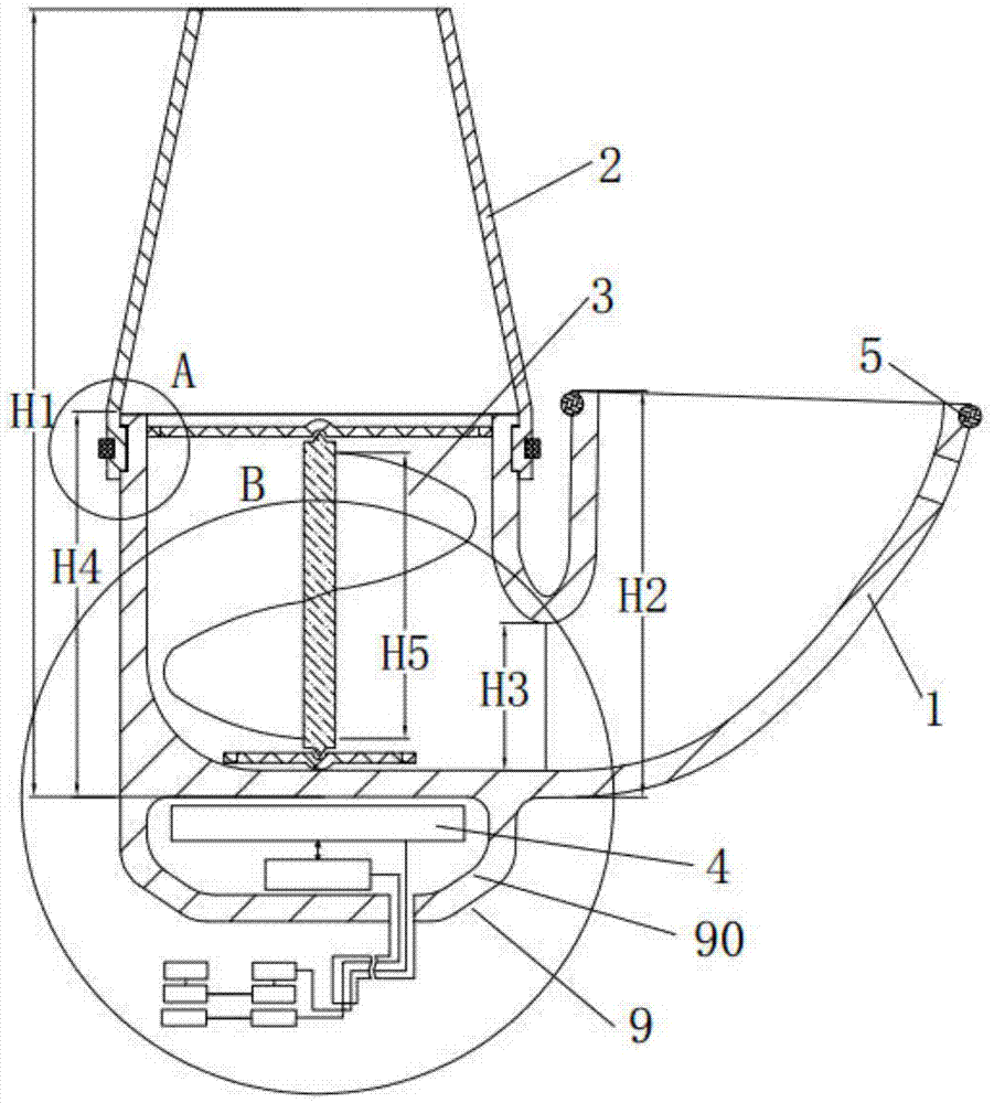
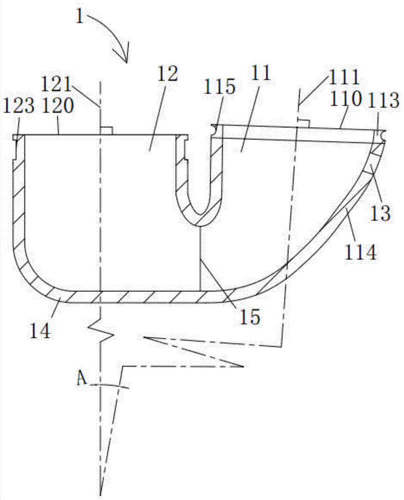
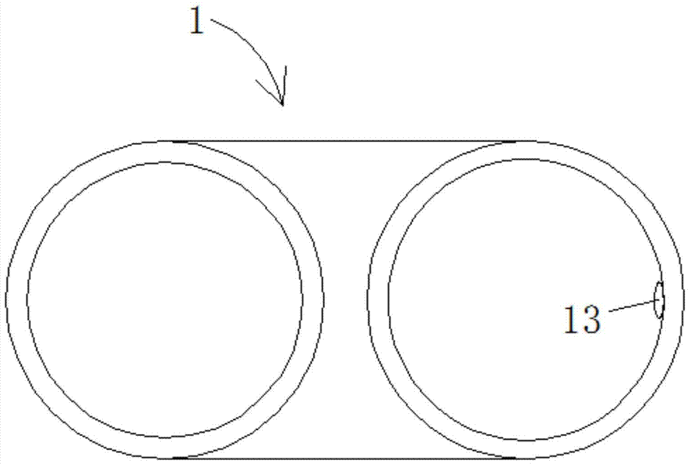
[0050] Please also refer to Figure 1 to Figure 5 as well as Figure 8 , the embodiment of the present invention provides a left ventricular assist device, which includes a connected first conduit 1 and a second conduit 2 , a blade 3 and a driving device 40 . The first pipeline 1 includes a connected inflow portion 11 and an outflow portion 12, the center perpendicular line of the inflow end surface 110 of the inflow portion 11 is the first perpendicular line 111, a...


PUM


Abstract

The invention discloses a left ventricular assist device, which comprises a connected first pipeline and a second pipeline, blades and a driving device; the first pipeline includes a connected inflow part and an outflow part, and the first An angle of 5° to 45° is formed between a central vertical line and the second central vertical line of the outflow end face of the outflow portion; the second pipeline includes an inflow port, an outflow port, and The overlapping portion between the outflow ports, the inflow port is detachably connected to the outflow end surface, the flow area of ​​the lap joint portion is greater than or equal to the flow area of ​​the outflow port; the blade is rotatably connected to the outflow portion inside; the outflow portion includes a bottom wall opposite to the outflow end surface, the blades and the driving device are respectively arranged on both sides of the bottom wall, and the driving device is used to drive the blades to rotate. The left heart assist device can be built into the heart cavity without damaging the heart structure.

Description

technical field [0001] The invention relates to the technical field of medical devices, in particular to a left heart assist device. Background technique [0002] For patients with left heart failure, when drug treatment is ineffective, a left ventricular assist device (Left ventricular assist device) is usually required, the purpose of which includes: (1) waiting for a donor and preparing for heart transplantation; (2) , restore heart function. [0003] Current left ventricular assist devices mainly include temporary left ventricular assist devices and long-term left ventricular assist devices. Temporary left ventricular assist devices include partial axial flow pumps and balloon pulsation devices, and their main features are percutaneous puncture or incision, and transvascular insertion. Long-term left ventricular assist devices include pneumatic pumps, centrifugal pumps and partial axial flow pumps. The blood is pumped into the aorta through artificial blood vessels. ...

Claims


Application Information

Patent Timeline
Patent Type & Authority Patents(China)
IPC IPC(8): A61M1/12A61M60/178A61M60/242A61M60/416A61M60/546A61M60/554A61M60/806A61M60/857A61M60/876
CPCA61M2210/125A61M60/148H02J50/005A61M60/876A61M60/806A61M60/242A61M60/546A61M60/554A61M60/178A61M60/416H02J7/00H02J2310/23A61M60/211
Inventor 丁枫
Owner 深圳市华畅医疗创新有限公司
Learn More