A Wireless Data Transmission Acquisition System with Large Capacity and Time Stamp

A technology of wireless data transmission and acquisition system, applied in the direction of integrated navigator, etc., can solve the problems of data congestion, rubidium atomic clock drift, packet loss and other problems, and achieve the effect of accurate filtering

Active Publication Date: 2019-03-26
CHINA ACADEMY OF SPACE TECHNOLOGY
View PDF14 Cites 0 Cited by
  • Summary
  • Abstract
  • Description
  • Claims
  • Application Information

AI Technical Summary

Problems solved by technology

[0005] (1) 10ns-level precise time synchronization and atomic clock time maintenance functions are not realized
[0006] (2) No noise reduction processing function for pulsar signal characteristics is not implemented
[0007] (3) There is no mention of multi-channel signal simultaneous acquisition function
[0008] (4) There is no large-capacity ping-pong storage function for high-speed data collection
[0009] (5) There is no wireless transmission function for short-term high-speed data exceeding 1Gbps
[0011] 4. Xu Wenquan of Xi'an Jiaotong University and others invented a pulsar frequency signal simulator (CN201210243095.0). This invention considers the GPS timing module, and the second pulse 1PPS output by the GPS timing module can synchronize the second pulse 1PPS of the random signal generator , in fact, the random signal generator does not have the function of accurately maintaining the clock for a long time, once there is no GPS signal, the clock will drift too much
Sun Jian of Xi'an Jiaotong University and others invented a pulsar-based time synchronization device (CN201210243058.X), which considered the signal of the rubidium atomic clock as the time reference for time interval measurement, but did not consider the drift of the rubidium atomic clock itself, which requires Time system reference sources such as GPS or BD for regular calibration and source tracking
[0012] 5. Li Zhenxin of Tianjin Institute of Aerospace Mechanical and Electrical Equipment and others invented "A Demonstration System for Ground Capture and Tracking of X-ray Pulsars" (CN201320618436.8), which considers the comprehensive control unit, demonstration unit, mobile platform, and detector orbit , light source, light source track, simulated detector, simulated earth, wireless transmission module and system power supply demonstration system, the wireless transmission module is designed for the winding of the cable during the rotation between the mobile platform and the detector track, but the invention It only starts from the visualization effect of the real process of X-ray pulsar signal acquisition, without mentioning the data acquisition rate and wireless transmission mechanism. Since the pulse arrival time data depends on the photon flow, it is sometimes dense and sometimes sparse. When the data is dense, the data capacity is large. , and the current Ethernet transmission has a 1G bps bottleneck limit, which will inevitably lead to data congestion and packet loss. Only through the FPGA internal high-frequency large-capacity bus (64-bit to 1024-bit AXI on-chip bus) can the data be transmitted to RAM for caching. In this process, it is also necessary to use a noise reduction algorithm to filter invalid data
"Spacecraft Navigation System of X-ray Pulsar Detector Equivalent" (CN201010022035.7), "X-ray Pulsar Navigation Embedded Simulation System Based on Semiconductor Laser" (CN200910023357.0) and "A System for Ground simulation scheme and device for X-ray pulsar navigation" (CN201010140837.8) lacks the acquisition of optical pulse signals and cannot realize physical simulation

Method used


Image

  • A Wireless Data Transmission Acquisition System with Large Capacity and Time Stamp
  • A Wireless Data Transmission Acquisition System with Large Capacity and Time Stamp
  • A Wireless Data Transmission Acquisition System with Large Capacity and Time Stamp

Examples


Embodiment Construction

[0053] Specific embodiments of the present invention will be further described in detail below in conjunction with the accompanying drawings.

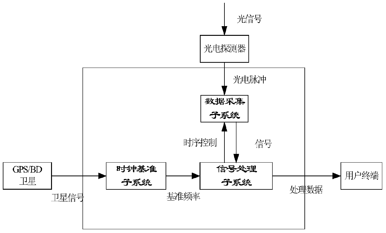
[0054] Such as figure 1 As shown, a large-capacity and time-stamped wireless data transmission acquisition system includes: a clock reference subsystem, a data acquisition subsystem and a signal processing subsystem;

[0055] The clock reference subsystem provides a time reference frequency signal to the signal processing subsystem; the time reference frequency signal includes a crystal oscillator signal, an atomic clock signal, and an atomic clock signal calibrated by a GPS or BD clock source;

[0056] The data acquisition subsystem, after low-pass filtering the multi-channel optical pulse signals, collects the filtered multi-channel optical pulse signals in real time at a sampling rate of 1Ghz according to the timing control logic sent by the signal processing subsystem, and outputs them to the signal processing sub-system system; ...


PUM


Abstract

The invention discloses a large-capacity wireless data transmission and collection system with a timestamp. The system comprises a clock reference subsystem, a data collection subsystem and a signal processing subsystem. The clock reference subsystem provides a time reference frequency signal. The data collection subsystem conducts low-pass filtering on multi-channel light pulse signals and then collects the filtered multi-channel light pulse signals at the sampling speed of 1 Ghz according to time sequence control logic sent by the signal processing subsystem. The signal processing subsystem conducts frequency multiplication on the time reference frequency signal to be used as a reference clock of the signal processing subsystem, conducts timestamp marking according to the light pulse collection signals output by the data collection subsystem according to the reference clock, then conducts ping-pang storage on data obtained after timestamp marking according to a certain protocol, and finally sends the stored data to a user terminal in a wireless transmission mode. The signal processing subsystem generates the time sequence control logic according to the reference clock and sends the time sequence control logic to the data collection subsystem.

Description

technical field [0001] The invention relates to a large-capacity and time-stamped wireless data transmission and collection system, which belongs to the technical field of time synchronization and data collection. Background technique [0002] As a key aerospace technology for future development, pulsar detection requires a large number of ground test verifications and on-orbit flight tests. Therefore, in the development of ground test verification systems, it is necessary to carry out technical research on X-ray pulsar photon arrival time measurement. Current prior art has following several kinds: [0003] 1. Sheikh et al. from the University of Maryland in the United States invented a system and method for realizing navigation by detecting pulsar radiation signals (United States Patent 7197381). In the invention, it is proposed to accurately measure the arrival time of the pulse signal, and then compare it with the standard pulse profile template. Thus, the position and s...

Claims


Application Information

Patent Timeline
Patent Type & Authority Patents(China)
IPC IPC(8): G01C21/24
CPCG01C21/24
Inventor 陈强帅平龙岩贝晓敏黄良伟吴耀军张倩傅灵忠
Owner CHINA ACADEMY OF SPACE TECHNOLOGY
Why Eureka
Try Eureka