Deslagging waste heat utilization device for circulating fluidized bed boiler

A circulating fluidized bed, slag waste heat technology, applied in fluidized bed combustion equipment, preheating, feedwater heaters, etc., can solve problems such as thermal deformation of slag discharge pipes, to solve thermal deformation, eliminate leakage, and reduce bottom cooling. Effect of slag temperature

Pending Publication Date: 2016-05-18
SHANXI GUOFENG COAL POWER CO LTD +1
View PDF0 Cites 5 Cited by
  • Summary
  • Abstract
  • Description
  • Claims
  • Application Information

AI Technical Summary

Problems solved by technology

[0003] The purpose of the present invention is to overcome the deficiencies of the above-mentioned prior art, and propose a slag discharge waste heat utilization device of a circulating fluidized bed boiler that can solve the problem of thermal deformation of the slag discharge pipe, prevent the inner pipe from being worn and leaked by the bottom slag, and reduce the temperature of the bottom slag.

Method used


Image

  • Deslagging waste heat utilization device for circulating fluidized bed boiler
  • Deslagging waste heat utilization device for circulating fluidized bed boiler
  • Deslagging waste heat utilization device for circulating fluidized bed boiler

Examples


Embodiment Construction

[0014] The following will clearly and completely describe the technical solutions in the embodiments of the present invention with reference to the accompanying drawings in the embodiments of the present invention. Obviously, the described embodiments are only some, not all, embodiments of the present invention. Based on the embodiments of the present invention, all other embodiments obtained by persons of ordinary skill in the art without creative efforts fall within the protection scope of the present invention.

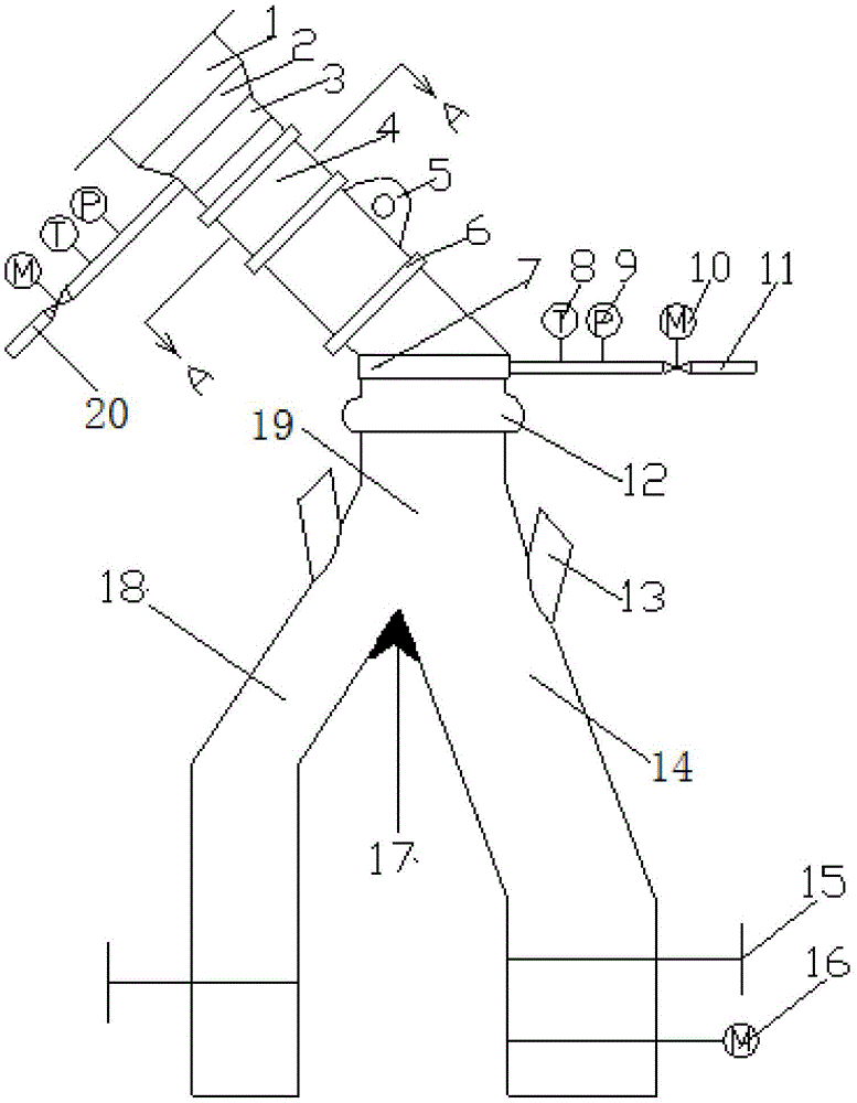
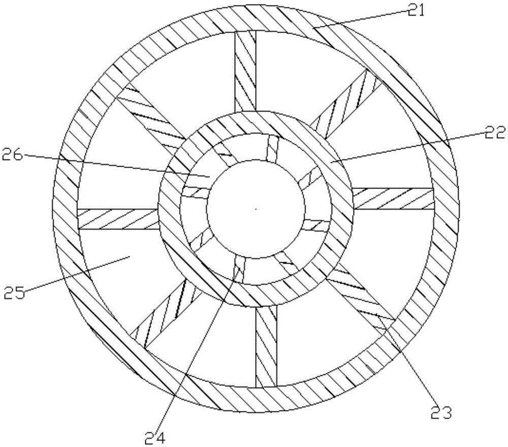
[0015] Such as Figure 1-4As shown, in the circulating fluidized bed boiler slagging waste heat utilization device in the embodiment, the slagging interface 2 is in the shape of a cone, the diameter of the upper port is larger than that of the lower port, the upper port is connected to the boiler slagging hole 1, and the lower port is connected to the collection port. The upper end of the box 3 is connected; the slag discharge heat exchange tube 4 is concentrically...


PUM


Abstract

The invention discloses a deslagging waste heat utilization device for a circulating fluidized bed boiler. By the adoption of the deslagging waste heat utilization device for the circulating fluidized bed boiler, the situations that heat deformation of a deslagging pipe is caused, and leakage is also caused due to the fact that an inner pipe is abraded by bottom slag are prevented. The deslagging waste heat utilization device for the circulating fluidized bed boiler comprises a deslagging hole, a deslagging connector, a collection header, a deslagging heat exchange pipe, a plurality of reinforcing ribbed plates, a distribution header, a cooling water inlet pipe, a cooling water outlet pipe, a three-dimensional expansion joint, a cooling air inlet, the deslagging pipe, a manual gate valve, an electric gate valve, an accident deslagging pipe, an underpant-shaped tee joint, an outer pipe, the inner pipe, a plurality of guide plates, pins and guide cavities. The deslagging connector is in a cone shape. The upper end opening of the deslagging connector is connected with the boiler deslagging hole, and the lower end opening of the deslagging connector is connected with the upper end of the collection header. An annular cavity is formed by the deslagging heat exchange pipe by concentrically sleeving the small-diameter inner pipe with the large-diameter outer pipe. The guide plates with the same width are welded between the wall of the inner pipe and the wall of the outer pipe, and the annular cavity is equally divided into the guide cavities not communicating with one another in the circumferential direction by the guide plates. The annular reinforcing ribbed plates which can prevent the deslagging heat exchange pipe against heating expansion and deformation are arranged on the outer wall surface of the outer pipe of the deslagging heat exchange pipe.

Description

technical field [0001] The invention relates to the field of circulating fluidized bed boilers, in particular to a device for utilizing waste heat from slagging of circulating fluidized bed boilers. Background technique [0002] In order to control the furnace bed pressure during operation of the circulating fluidized bed boiler, prevent the deposition of large particle materials, maintain a good fluidized state, and avoid slagging, the bottom slag must be discharged from the slag discharge hole at the bottom or lower side of the boiler in a timely manner. The amount of bottom slag discharged from circulating fluidized bed boilers in actual operation is large, complex in composition, poor in fluidity, coarse in particle size, and may contain many large particles of foreign matter. Cooling, the physical heat loss of the bottom slag can reach more than 1%, and the temperature of the bottom slag is too high, which is not conducive to the safe and stable operation of the subsequ...

Claims


Application Information

Patent Timeline
IPC IPC(8): F22D1/00F23C10/18
CPCF22D1/00F23C10/18
Inventor 柳成亮李东雄申海文徐鸿恩张晓宇田宇
Owner SHANXI GUOFENG COAL POWER CO LTD
Why Eureka
Try Eureka