Pressure ring
A pressure ring and ring-shaped technology, which is applied in the field of pressure rings, can solve the problems of ring groove wear and aluminum to the pressure ring, and achieve the effect of inhibiting fixation
- Summary
- Abstract
- Description
- Claims
- Application Information
AI Technical Summary
Problems solved by technology
Method used
Image
Examples
no. 1 approach
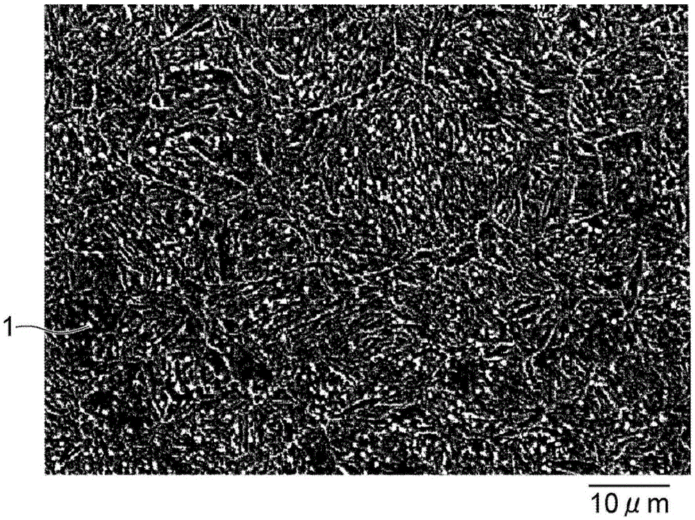
[0033] The pressure ring of the first embodiment is a piston ring for an internal combustion engine (for example, an automobile engine). The pressure ring is fitted into, for example, a ring groove formed on a side surface of a cylindrical piston included in an internal combustion engine. The piston is inserted into the combustion chamber (cylinder) of the engine. In particular, the pressure ring can also be a ring that is exposed to an environment with a high thermal load on the engine.
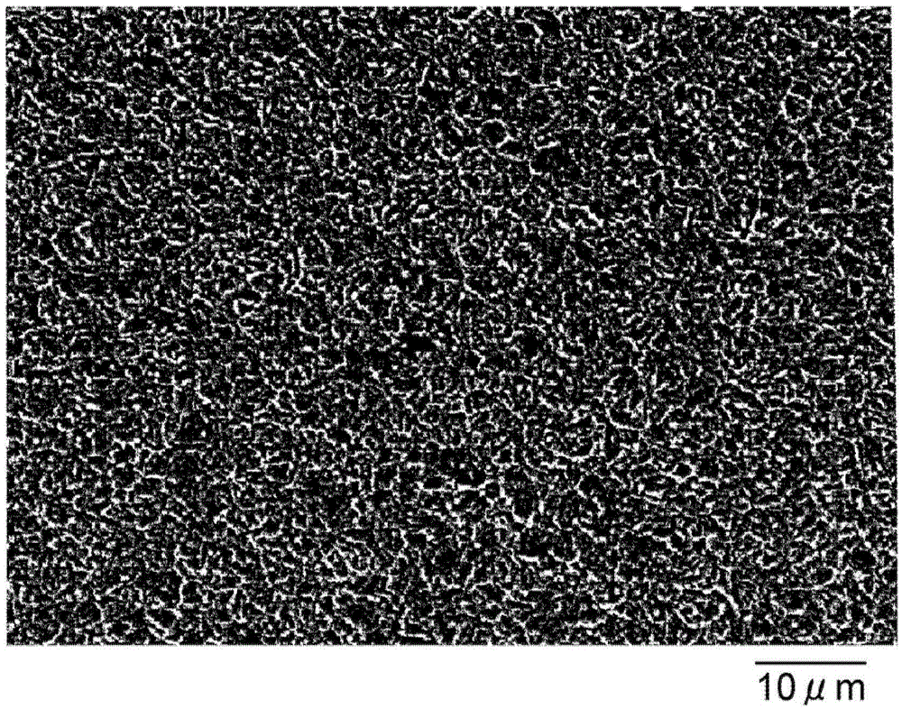
[0034] The structure of the pressure ring of this embodiment will be described. Such as Figure 6 , Figure 7 a and Figure 7 As shown in b, the pressure ring 11 includes an annular body portion 12 (base material) and a first membrane 14 . An opening 13 is formed in the ring-shaped main body 12 . That is, "annular" does not necessarily mean a closed circle. The ring-shaped main body portion 12 may be a perfect circle or an ellipse. The main body part 12 has the planar side surfaces 1...
no. 2 approach
[0064] The pressure ring of the second embodiment is the same as the pressure ring of the first embodiment except that the steel material constituting the main body part contains Cu. Hereinafter, only the unique features of the pressure ring of the second embodiment will be described.
[0065] The main body portion 12 of the pressure ring according to the second embodiment is made of a steel material consisting of 0.45 to 0.55% by mass of C, 0.15 to 0.35% by mass of Si, 0.65 to 0.95% by mass of Mn, and 0.80 to 1.10% by mass of Cr. , 0.25% by mass or less of V, less than 0.010% by mass of P, 0.02 to 0.25% by mass of Cu (copper), and the remainder including Fe and unavoidable impurities. The content of Cu in the steel may be 0.02-0.25 mass%, 0.02-0.20 mass%, 0.02-0.16 mass%, 0.04-0.25 mass%, 0.04-0.20 mass%, 0.04-0.16 mass%, or 0.16-0.25 mass% .
[0066] In the manufacture of the pressure ring of the second embodiment, the wire rod is produced by drawing a steel material, as i...
Embodiment 1
[0070] (Examples 1 to 4, Comparative Example 1)
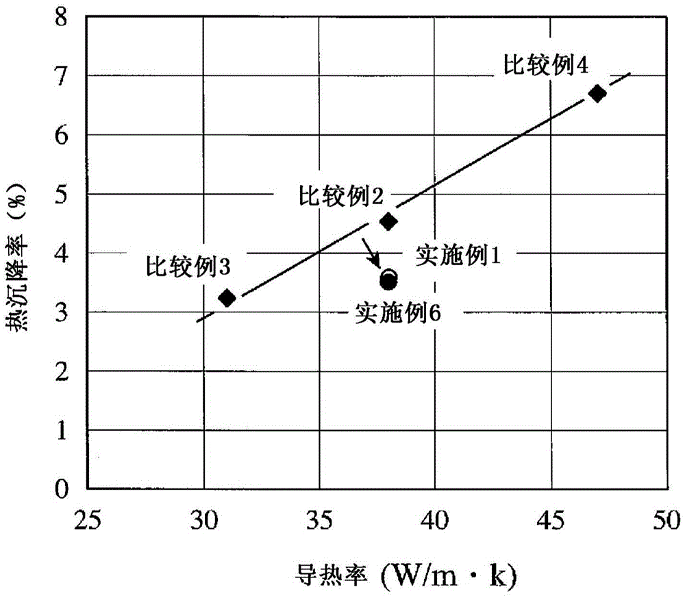
[0071] Using steel materials J1, J2, J3, J4, and C1 each having a composition shown in Table 2 below, pressure rings were fabricated by the following method. It should be noted that all the steel materials naturally contain iron in addition to the elements shown in Table 2 below. The pressure ring using the steel material J1 is Example 1. The pressure ring using steel material J2 is Example 2. The pressure ring using steel material J3 is Example 3. The pressure ring using steel material J4 is Example 4. The pressure ring using steel material C1 is Comparative Example 1. Steel C1 is equivalent to SUP10. Hereinafter, Example 1 will be referred to as J1, Example 2 will be referred to as J2, Example 3 will be referred to as J3, Example 4 will be referred to as J4, and Comparative Example 1 will be referred to as C1 depending on the circumstances.
[0072] The drawing process is carried out on the steel material. In the wire ...
PUM
| Property | Measurement | Unit |
|---|---|---|
| Thickness | aaaaa | aaaaa |
| Thermal conductivity | aaaaa | aaaaa |
| The average particle size | aaaaa | aaaaa |
Abstract
Description
Claims
Application Information
 - R&D
- Intellectual Property
- Life Sciences
- Materials
- Tech Scout
- Unparalleled Data Quality
- Higher Quality Content
- 60% Fewer Hallucinations
Browse by: Latest US Patents, China's latest patents, Technical Efficacy Thesaurus, Application Domain, Technology Topic, Popular Technical Reports.
© 2025 PatSnap. All rights reserved.Legal|Privacy policy|Modern Slavery Act Transparency Statement|Sitemap|About US| Contact US: help@patsnap.com


