
Novel fiber high-voltage sensor

A high-pressure sensor, sensor technology, applied in instruments, fluid pressure measurement using optical methods, fluid pressure measurement, etc., can solve the problems of unavoidable noise interference and temperature drift, high maintenance costs, difficult deployment, etc., to achieve anti-electromagnetic The effect of strong interference, low processing cost and low power consumption

Active Publication Date: 2016-05-11
TIANJIN QIU SHI FIBER TECH
View PDF5 Cites 2 Cited by
  • Summary
  • Abstract
  • Description
  • Claims
  • Application Information

AI Technical Summary

Problems solved by technology

[0003] In the existing technology, electronic pressure sensors are widely used. This kind of sensor has problems such as difficult to avoid noise interference and temperature drift, large volume, short life, difficult deployment, and high maintenance costs.
Optical fiber sensors have many advantages such as anti-electromagnetic interference, good electrical insulation, corrosion resistance, high sensitivity, light weight, small size, variable shape, and easy reuse. They are very suitable for high-voltage detection, but there is currently no F-P interference Optical fiber high voltage sensor under the principle technology platform

Method used


Image

  • Novel fiber high-voltage sensor
  • Novel fiber high-voltage sensor
  • Novel fiber high-voltage sensor

Examples


Embodiment Construction

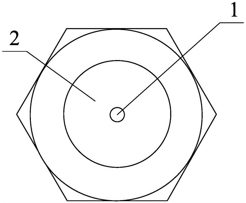
[0028] Such as figure 1 , 2 , 3, the novel optical fiber high pressure sensor of the present invention comprises a pressure inlet 1, a pressure source connector 2, a base 3, a casing 4, an optical cable waterproof connector 5, a sensing diaphragm 6, a multimode optical fiber 7, and an SMA metal optical fiber ferrule 8 , Armored fiber optic jacket 9.

[0029] The sides of the SMA metal optical fiber ferrule 8 and the base 3 are sealed by evenly applying epoxy resin, and the bottom surface is connected by laser welding; the sensing diaphragm 6 is a square diaphragm with a cylindrical Farper microcavity, and the SMA metal optical fiber ferrule The cores 8 are fixed by epoxy resin, and the signal quality is observed through the polarization low-coherence interference demodulation unit 18 before fixing to ensure the alignment of the diaphragm and the ferrule; the sides of the pressure source connector 2 and the base 3 are evenly coated with epoxy resin Sealed with glue, the botto...


PUM


Abstract

The invention provides a novel fiber high-voltage sensor, including a pressure inlet, a pressure source joint, a base, a shell, an optical cable waterproof joint, a sensing diaphragm, a multimode fiber, an SMA metal optical fiber core and an armored optical fiber jacket. The SMA metal optical fiber insertion core and side faces of the base are sealed through uniform smearing of epoxy resin glue, and a bottom surface is connected through laser welding; the sensing diaphragm is a square diaphragm with a cylindrical Fabry-Perot microcavity, the sensing diaphragm and the SMA metal optical fiber insertion core are fixed through epoxy resin, and before fixing, signal quality is observed through a polarization low-coherent interference interrogator to ensure the alignment property of the diaphragm and the insertion core; the pressure source joint and the side faces of the base are sealed through uniform smearing of epoxy resin glue, and the bottom surface is connected through laser welding; and the base and the shell are connected through threads, and the shell and the optical cable waterproof joint are connected through threads. The novel fiber high-voltage sensor is wide in range of application, strong in anti-electromagnetic interference, and low in power consumption, has relatively low requirement for a light source, and is simple in structure, convenient to maintain and low in cost.

Description

technical field [0001] The invention belongs to the field of optical fiber sensing, in particular to a novel optical fiber high voltage sensor. Background technique [0002] In high-voltage engineering fields such as marine monitoring, petroleum, and chemical engineering, environmental pressure is an important monitoring content, which is directly related to the accuracy of monitoring data, the safety of the production environment, and the quality of industrial products. [0003] Electronic pressure sensors are widely used in the existing technology. Such sensors have problems such as difficulty in avoiding noise interference and temperature drift, large volume, short life, difficult deployment, and high maintenance costs. Optical fiber sensors have many advantages such as anti-electromagnetic interference, good electrical insulation, corrosion resistance, high sensitivity, light weight, small size, variable shape, and easy reuse. They are very suitable for high-voltage dete...

Claims


Application Information

Patent Timeline
IPC IPC(8): G01L11/02
CPCG01L11/025
Inventor 刘柯
Owner TIANJIN QIU SHI FIBER TECH
Learn More