A teo0n/teo1n mode exciter

A mode excitation and ladder wave technology, applied to waveguide devices, electrical components, circuits, etc., can solve the problems of large device size, insufficient flexibility, and high cost, and achieve the effects of simple processing, strong scalability, and compact structure

Active Publication Date: 2018-04-06
UNIV OF ELECTRONICS SCI & TECH OF CHINA
View PDF2 Cites 0 Cited by
  • Summary
  • Abstract
  • Description
  • Claims
  • Application Information

AI Technical Summary

Problems solved by technology

For example, the cross-shaped converter disclosed in "Journal of Vacuum Science and Technology, 2013, Vol. 33 (4), 309-314", although its operating frequency bandwidth is wide, the output The mode has high purity, but it needs to be produced by electroforming, the device is large in size and expensive
And the H-plane bending mode converter disclosed in ""Strong Laser and Particle Beam", 2014, Volume 26 (6)", the exciter conversion efficiency of this structure is above 95%, and the mode purity is above 98% The relative bandwidth can reach 4.2GHz. Although the bandwidth and mode purity are relatively high, the structure is simple but the flexibility is not enough, and it is inconvenient to convert to a higher-order mode.

Method used


Image

  • A teo0n/teo1n mode exciter
  • A teo0n/teo1n mode exciter
  • A teo0n/teo1n mode exciter

Examples


Embodiment Construction

[0019] In order to make the purpose, technical solution and advantages of the present invention clearer, the present invention will be further described in detail below in conjunction with the implementation methods and accompanying drawings.

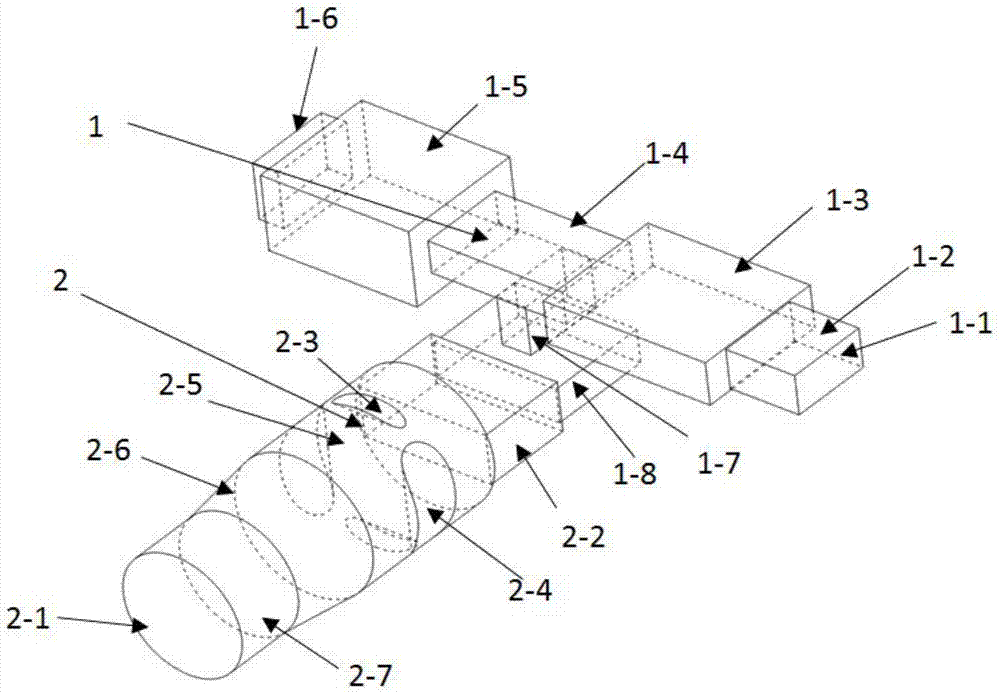
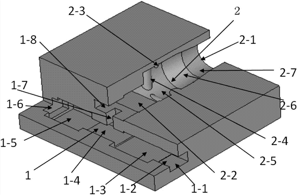
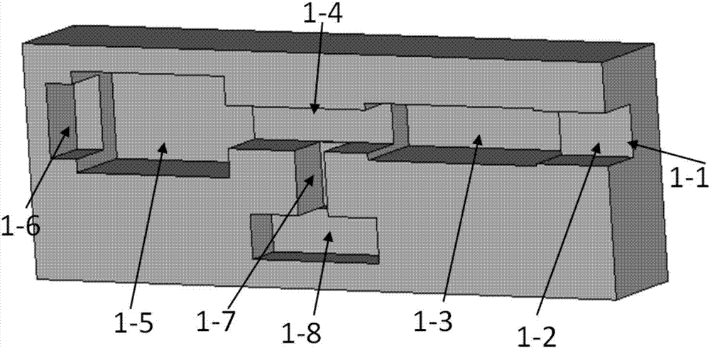
[0020] to work in the Q-band The exciter is an embodiment to describe the present invention in detail. The structure of the exciter of this embodiment can be found in figure 1 , 2 , mainly including: an input port 1-1 connected to a standard rectangular waveguide, an output port 2-1 connected to a high-frequency structure, a first-order matching ladder waveguide 1-3 (matched with 1-2), a second first-order waveguide Matching ladder waveguide 1-5 (matching with 1-4), third first-order matching ladder waveguide 2-2 (matching with 1-8), first rectangular waveguide 1-2, second rectangular waveguide 1-4, third Rectangular waveguide 1-8, coupling hole 1-7, short-circuit surface 1-6, cylindrical ridge 2-3, 2-4 (for ease of description, in ...


PUM


Abstract

The invention discloses a mode exciter: one end of the first rectangular waveguide (1-2) is connected to the input port (1-1), and the other end is connected to the first first-order matching ladder waveguide (1-3); the second rectangular waveguide ( One end of 1-4) is connected to the first first-order matching ladder waveguide (1-3), one end is connected to the second first-order matching ladder waveguide (1-5), and the other end of the second first-order matching ladder waveguide (1-5) is the short-circuit surface (1-6); one end of the third rectangular waveguide (1-8) is connected to the side wall of the second rectangular waveguide (1-4) through the coupling hole (1-7), and one end is connected to the third first-order matching Ladder waveguide (2‑2); one end of the first circular waveguide (2‑5) is connected to the third first-order matching ladder waveguide (2‑2), and one end is connected to the tapered circular waveguide (2‑6); the second circular waveguide One end of the waveguide (2-7) is connected to the tapered circular waveguide (2-6), and the other end is connected to the output port (2-1); the inner wall of the first circular waveguide (2-5) is provided with symmetrical ridges of different sizes. The invention has small reflection, high mode purity and wide working bandwidth.

Description

technical field [0001] The invention belongs to the field of microwave and millimeter wave technology, and in particular relates to a mode excitation device for cold measurement of a high-frequency system of a cyclotron amplifier, a cycloklystron and a cyclotron oscillation tube. Background technique [0002] Mode converters have important applications in microwave and millimeter wave communications, testing, and solid-state power combining. In recent years, great progress has been made in the development of cyclotron amplifiers (including cyclotron traveling wave tubes and cyclotron klystrons) and cyclotron oscillator tubes at home and abroad. The working mode output by the gyrotron cavity is generally not suitable for direct use, so the performance of the system cannot be verified. Therefore, it is often necessary to convert these modes into a form that is convenient for direct use through mode conversion, so it is necessary to design a mode exciter to control the gyrotron...

Claims


Application Information

Patent Timeline
Patent Type & Authority Patents(China)
IPC IPC(8): H01P1/163
CPCH01P1/163
Inventor 刘国王燕罗勇王建勋鄢然蒲友雷徐勇蒋伟
Owner UNIV OF ELECTRONICS SCI & TECH OF CHINA
Why Eureka
Try Eureka