Eureka AIR delivers breakthrough ideas for toughest innovation challenges, trusted by R&D personnel around the world.

A catenary status online monitoring/detection device based on public network transmission

A detection device and catenary technology, applied in measurement devices, instruments, etc., can solve the problem of large errors in monitoring results, limitations of working time and methods, and inability to achieve full-time, unmanned, and independent monitoring/detection processes. problems, to achieve the effect of strong adaptability, improvement of technical support capabilities, and independent real-time online monitoring/detection

Active Publication Date: 2018-04-20
WUHAN UNIV +2
View PDF14 Cites 0 Cited by
  • Summary
  • Abstract
  • Description
  • Claims
  • Application Information

AI Technical Summary

Problems solved by technology

Invention patent CN102759347 B discloses a high-speed rail catenary online inspection device, inspection method and a high-speed rail catenary detection system composed of it. The inspection device includes a high-speed camera module and a vehicle-mounted server connected to the high-speed camera module. Its characteristics are : Convert the collected video into synchronous catenary pictures and position pictures, and then use the algorithm to analyze and process the detected results; however, this system can only collect the image information of the catenary, but cannot collect other mechanical physics or The parameters of its environment, the collected information is not comprehensive enough, not true enough, and the reference value is not large enough. At the same time, the system is a vehicle-mounted inspection system, which belongs to the traditional monitoring / detection technology category, and cannot realize the all-day monitoring / detection process , unmanned, independent, with huge restrictions on working hours and methods
Invention patent CN104567684 A discloses a catenary geometric parameter detection method and device. The device includes at least two scanning cameras fixed on the top of the vehicle. and at least two line scan cameras relative to the position data of the top of the vehicle to determine the geometric parameters of the catenary; however, the device and method are only aimed at the detection of the geometric parameters of the catenary, the collection of information involves a narrow range, and the data processing process is complex and prone to distortion. Simultaneous detection The cost is high, the results are random, not large, universal, continuous, easily affected by weather factors, and cannot be monitored online in real time
Invention patent CN105067041 A discloses a catenary state monitoring device and its control method. The device includes a dual light source transmitting module, an optical circulator, an optical signal demodulation module, a control module, a computer terminal, and a fiber grating sensor. Its characteristics are: Real-time monitoring of catenary temperature and vibration is realized through the sensing characteristics of optical fiber and fiber Bragg grating; however, because its fiber optic grating sensor and long-distance sensing optical fiber are laid along the catenary line, the laying cost is huge, and its installation and construction affect the catenary system The normal operation of the train brings inconvenience to the train. At the same time, due to the long-distance laying of the sensing optical fiber, it will inevitably receive more external interference, so that the error of the monitoring result is relatively large. In addition, the light source and the receiving terminal are placed on the ground, so it has been destroyed by human factors
[0015] Generally speaking, there are not many researches on the state monitoring / detection of high-speed railway catenary, and most of them belong to the research on traditional monitoring / detection technology. The carriers of the monitoring / detection components in the research are all vehicles. The function is single, and the catenary status information obtained is less, and most of them can only obtain the instantaneous state of the catenary at the detection moment. The monitoring / detection of the catenary status is intermittent and discontinuous, and it is impossible to realize the real-time online operation status of the catenary. Continuous Monitoring / Detection

Method used


Image

  • A catenary status online monitoring/detection device based on public network transmission
  • A catenary status online monitoring/detection device based on public network transmission
  • A catenary status online monitoring/detection device based on public network transmission

Examples


Embodiment

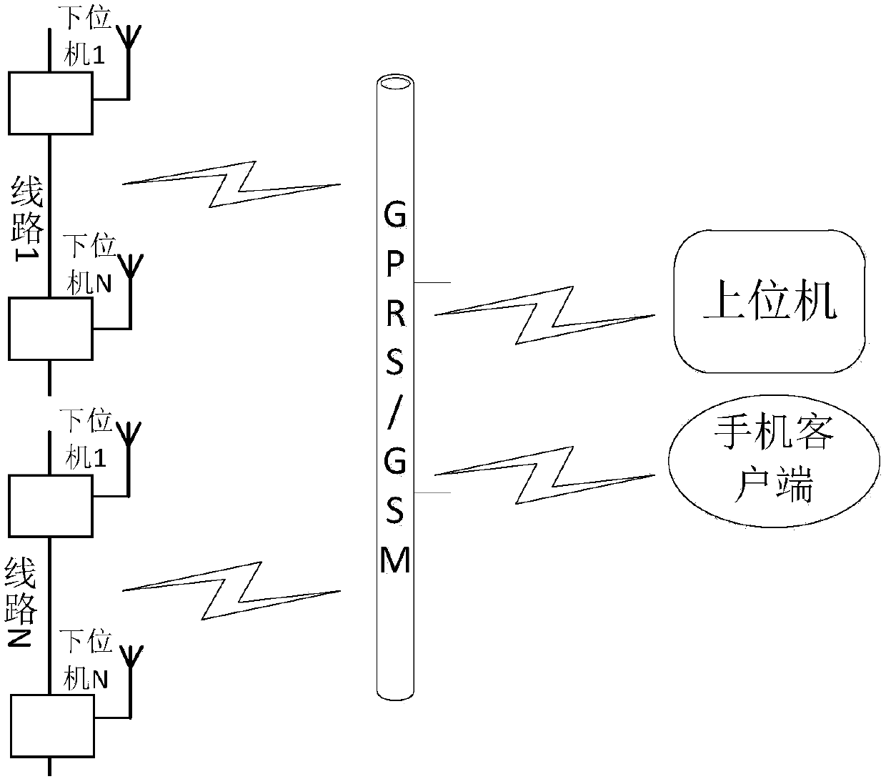
[0065] Such as figure 1 Shown is the hierarchical distribution diagram of the device of the present invention. A host computer located in the remote control room can connect all the lower computers installed on the catenary line through the GPRS / GSM wireless network at the same time. Each catenary monitoring line will have a number corresponding to it. Multiple lower computers are installed on the line, and each lower computer has a set of codes including the line code and its own code, so that all the upper computers can be classified according to the different installation lines in the upper computer node operation panel. It is not only easy to operate, but also convenient for subsequent data analysis and calculation. The upper computer can send control instructions to the lower computer in the two modes of high-speed data transmission and low-speed data transmission of the system, and at the same time can extract the required sampling data from the corresponding upper comp...


PUM


Abstract

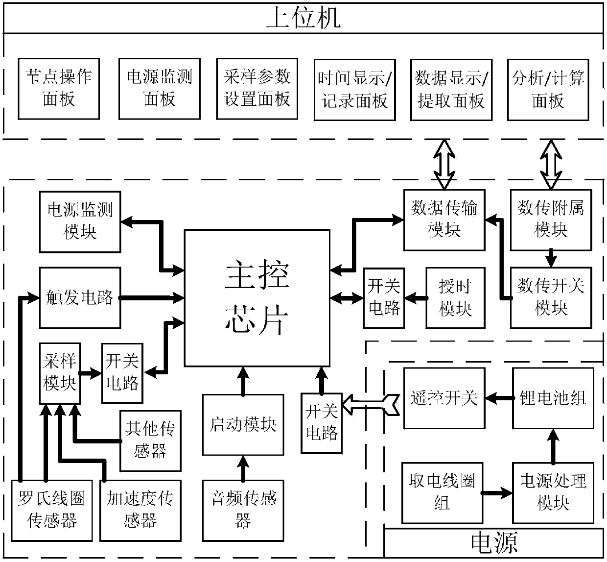
The invention discloses a contact network state on-line monitoring / detection device based on public network transmission, comprising a plurality of lower computers and remote upper computers which are installed on a return circuit; the upper computers communicate with the lower computers through a GPRS / GSM wireless network; and a mobile phone can control part of the functions of the lower computers. The remote computer comprises a node operation panel, a power supply monitoring panel, a sampling parameter configuration panel, a time display / recording panel, and a data display / extraction and analysis / computer panel; the lower computer comprises a main control chip, a trigger circuit, a switch circuit, a sampling module, a power supply monitoring module, a data transmission module, a data transmission auxiliary module, a data transmission switch module, a time service module, a start-up module, an audio sensor module, a state monitoring sensor module, and a self-power supply module. The lower computer utilizes various sensors to collect the state parameters of the contact network structure, current, environment and the internal of the device, and the upper computer displays the obtained state parameters in the panels and records to finally generate a technology report. The invention can collect various state parameters, and realizes full-day, unmanned and independent work.

Description

technical field [0001] The invention belongs to the technical field of state parameter measurement of a railway catenary system, and relates to an online catenary state monitoring / detection device based on public network transmission. Background technique [0002] The development of railway speed has gone through the process from steam era, internal combustion era to electric era. Speed ​​increase cannot be separated from electrified railway. Railway electrification is the ultimate goal of China's railway development. The main factors affecting the running speed of the train are not only the radius of the line curve, seamless steel rail, traction locomotives, train vehicles, etc., but also the quality of the catenary is an important factor affecting the running speed of the train. [0003] The catenary is a special form of transmission line erected along the railway line to supply power to the electric locomotive. The catenary is responsible for the important task of directl...

Claims


Application Information

Patent Timeline
Patent Type & Authority Patents(China)
IPC IPC(8): G01D21/02
CPCG01D21/02
Inventor 肖晓晖杨帆戚广枫李红梅方志国游鹏辉
Owner WUHAN UNIV
Why Eureka
Eureka Blog
Learn More