
Electric power supplying device and harness routing structure using the same

A power supply, flat wire technology, applied in arrangements using take-up reels/photosensitive drums, arrangements using expandable carriers, cable arrangements between relatively moving parts, etc., can solve redundant length absorption performance variations. It can improve the absorption function of redundant length or the absorption performance of redundant length, and improve the absorption performance.

Active Publication Date: 2011-06-01
YAZAKI CORP
View PDF6 Cites 20 Cited by
  • Summary
  • Abstract
  • Description
  • Claims
  • Application Information

AI Technical Summary

Problems solved by technology

[0005] When the spring 59 is not used, only the outermost diameter portion of the flat wire harness 52 is largely enlarged in diameter to come into contact with the inner surface of the housing 53, so that the redundant length absorption performance of the flat wire harness 52 is deteriorated due to its frictional resistance.

Method used


Image

  • Electric power supplying device and harness routing structure using the same
  • Electric power supplying device and harness routing structure using the same
  • Electric power supplying device and harness routing structure using the same

Examples


Embodiment Construction

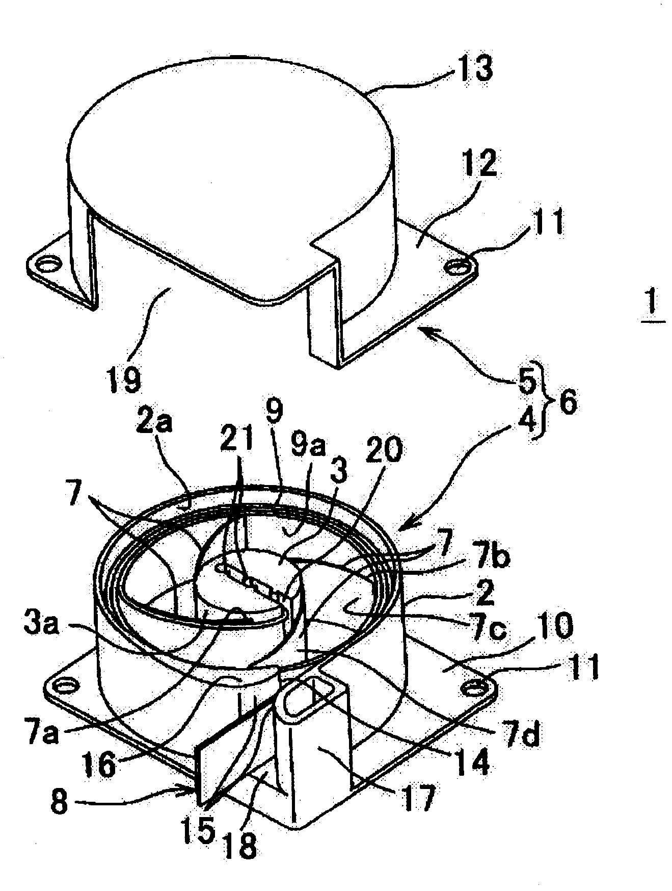
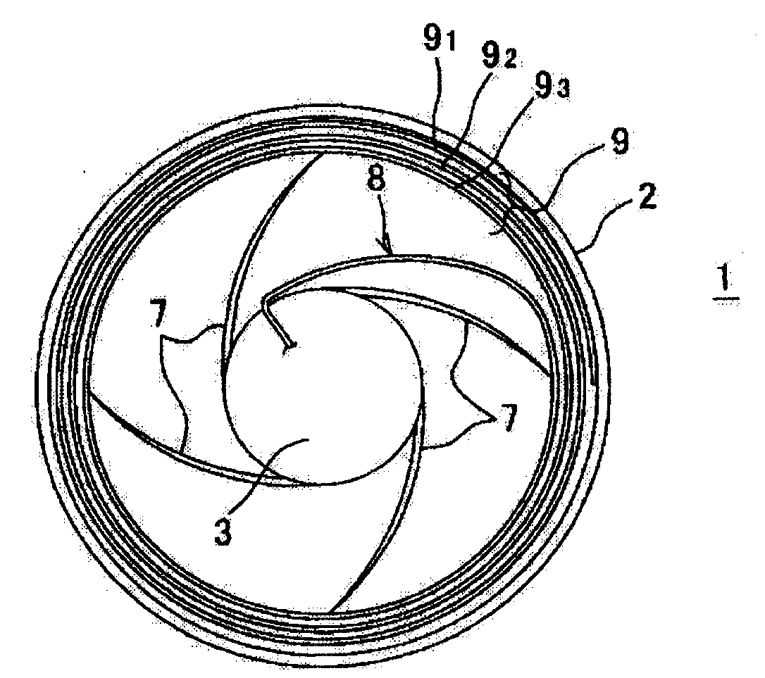
[0067] Figure 1 to Figure 2 An exemplary embodiment of a power supply device according to the invention is shown.

[0068] Such as figure 1 As shown, the power supply device 1 includes: a housing 6 made of synthetic resin and having a circular annular portion (annular wall) 2 and a cylindrical boss portion 3 as its center; a plurality of plate-shaped spring members 7 radially arranged on the outer periphery; and a flexible flat wire harness 8 accommodated in a state in which the inner diameter portions 9a of the winding portions 9 are respectively pushed by the spring members 7 and the flat wire harness The diameter increases annularly along the inner peripheral surface 2 a of the annular portion 2 .

[0069] The housing 6 has a base 4 and a cover 5 . The base portion 4 is preferably integrally formed with the annular portion 2 and the boss portion 3 vertically provided on the base plate portion 10 . The cover portion 5 is formed by a horizontal base plate portion 12 whi...


PUM


Abstract

An electric power supplying device adapted such that a flat wire harness is spirally wound so that the wire harness is increased or decreased in diameter to absorb an excessive length of the wire harness, wherein the electric power supplying device has increased performance of absorbing the excessive length of the wire harness, has a simplified structure, and is of low cost. An electric power supplying device (1, 31) is adapted such that a flat wire harness (8) is multiply wound about a boss (3), a spring member (7, 22) is mounted so as to extend from the boss to an inner diameter section (9a) of a wound section (9) of the wire harness, the wound section is outwardly urged by the spring member, and the wire harness is arranged with a small pitch in the radial direction. The spring member (7, 22) is composed of radially arranged curved plate springs or is a spiral spring curved in a loop shape. The boss (3), the wound section (9), and the spring member (7, 22) are contained on the inner side of an annular wall (2) of a case (6). Curved surfaces (15) for guiding the wire harness are formed on opposite sides of a harness lead-out opening (14) in the annular wall (2).

Description

technical field [0001] The present invention relates to a power supply device and a wire harness arrangement structure using the same, in which a flat wire harness is helically wound to absorb a redundant length of the wire harness and straightly drawn out to satisfy movable movement of the structure. Background technique [0002] Figure 10 An example of a conventional power supply device is shown (see Patent Document 1). [0003] The power supply device 51 includes: a rectangular housing 53 that spirally accommodates the flat wire harness 52; a disk 54 that supports the helical portion 52a of the flat wire harness 52 in the housing; a central shaft 55 that supports the innermost diameter portion of the helical portion 52a; A plurality of rotating rollers 56 whose outermost diameter portions come into contact; and springs 59 respectively supporting the rollers 56 along the slits 57 of the housing 53 via pin portions 58 to urge the rollers toward the center of the wire harn...

Claims


Application Information

Patent Timeline
IPC IPC(8): H02G11/02B60R16/02H02G11/00
CPCH02G11/006B60R16/0215H02G11/02B60R16/027
Inventor 椿章
Owner YAZAKI CORP
Learn More