
Self-calibration method of converter IGBT power module junction temperature measurement

A power module and converter technology, which is applied in the field of self-calibration of converter IGBT power module junction temperature measurement, can solve the problems of IGBT module safety performance impact, IGBT saturation voltage drop difficulty, device junction temperature calibration measurement, etc. The effect of reducing cost and technical difficulty, high sensitivity, and easy measurement

Active Publication Date: 2016-04-20
TONGJI UNIV
View PDF4 Cites 16 Cited by
  • Summary
  • Abstract
  • Description
  • Claims
  • Application Information

AI Technical Summary

Problems solved by technology

This method does not affect the normal operation of the system, but it also has certain limitations: first, the IGBT saturation voltage drop is not sensitive to temperature within a certain current range, so this method cannot calibrate and measure the device junction temperature in all operating intervals; in addition , because the IGBT saturation voltage drop is very small (usually 1-2V) and the turn-off voltage drop is large (usually several hundred volts), so the IGBT saturation voltage drop is accurately calibrated and measured under the high-frequency switching working condition of the converter very difficult
However, this method requires an additional test circuit and cannot be directly used in the actual system, and the calibration process may affect the safety performance of the IGBT module in the converter

Method used


Image

  • Self-calibration method of converter IGBT power module junction temperature measurement
  • Self-calibration method of converter IGBT power module junction temperature measurement
  • Self-calibration method of converter IGBT power module junction temperature measurement

Examples


Embodiment

[0034] Detection object: IGBT device in power module FF50R12RT4

[0035] Self-calibration experiment process:

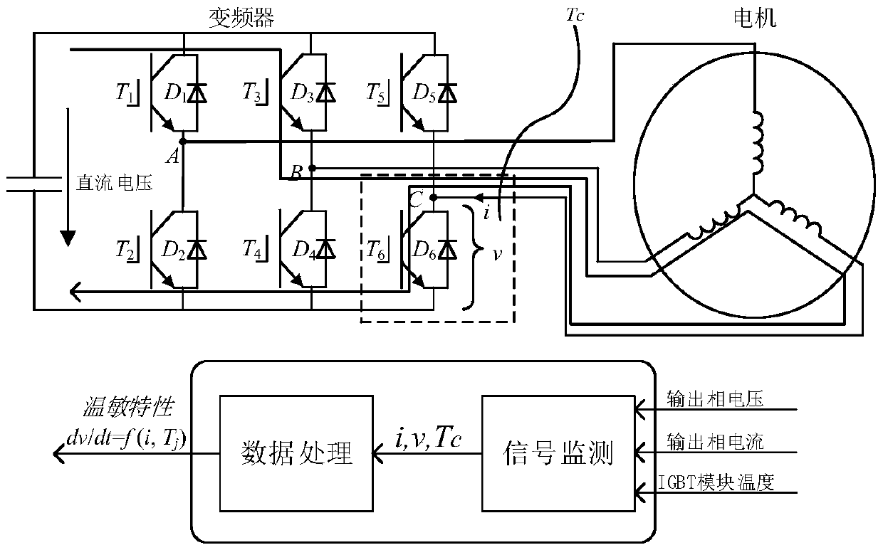
[0036] The self-calibration experimental system for measuring the junction temperature of the inverter IGBT module is as follows: figure 1 shown.

[0037] 1) Inverter self-heating: set the device under test as IGBTT 6 , the B and C phase half-bridges in the inverter and the motor windings form an H-bridge circuit, and by controlling the corresponding IGBT (T3 , T 4 , T 5 , T 6 ) gate trigger signal to generate a certain DC load current to heat the IGBT power module to make its temperature reach a specified value (such as 135°C). In order to ensure the safety of the inverter, the load DC current value should be lower than the rated current of the inverter. Keep it for a period of time (about 1s~10s), and when the internal heat balance of the power module is reached, the gate signal is blocked to cut off the load current, so that the inverter is in the cooling st...


PUM


Abstract

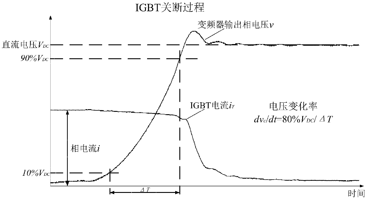
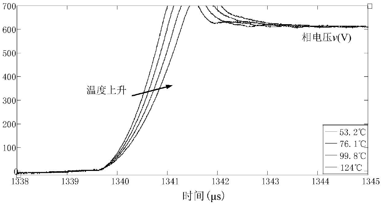
The invention relates to a self-calibration method of converter IGBT power module junction temperature measurement. The self-calibration method comprises the following steps that: 1) the three-dimensional temperature sensitive characteristic table of an IGBT module is obtained; and 2) the operating junction temperature of the IGBT module is calculated according to the three-dimensional temperature sensitive characteristic table dv / dt=f(Tj,i) as well as actually measured operating current and voltage data of the IGBT module to be measured. The step 1) further includes the following steps that: 11) self heating of a converter is carried out: with a converter cooling device turned off, the converter is loaded through a load under control, so that the temperature of the IGBT module is increased gradually to achieve an instruction value; 12) after self heating is completed, IGBT gate signals are locked, load current is cut off, and therefore, the temperature Tc of the IGBT module after self heating is completed can be slowly decreased to ambient temperature; and 13) in a process in which the temperature of the IGBT module is slowly decreased to the ambient temperature, current scanning and temperature scanning of a double-pulse test are performed on the IGBT module, so that the three-dimensional temperature sensitive characteristic table dv / dt=f(Tj,i) of the IGBT module based on voltage change rate dv / dt can be obtained. Compared with the prior art, the self-calibration method of the invention has the advantages of suitability for industrial sites, simple measurement, accurate measurement and the like.

Description

technical field [0001] The invention relates to the field of junction temperature measurement of power electronic devices, in particular to a self-calibration method for measuring the junction temperature of a converter IGBT power module. Background technique [0002] Junction temperature is an important state variable of power electronic devices in IGBT power modules, which can directly reflect device safety margin, health status and operating performance. However, due to the closed structure of the module, the small size of the device chip, the uneven temperature distribution, and the high voltage, high current, and high frequency operation of the converter, it is very difficult to measure the junction temperature of the IGBT module. As the core component of the converter, it is of great engineering significance to develop a simple, accurate and safe IGBT module junction temperature measurement technology for converter performance evaluation, optimal design, status monitor...

Claims


Application Information

Patent Timeline
Patent Type & Authority Applications(China)
IPC IPC(8): G01R31/26G01K13/00
CPCG01K13/00G01R31/26
Inventor 向大为袁逸超
Owner TONGJI UNIV
Learn More