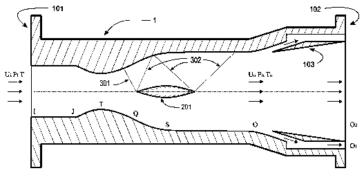
Supersonic-speed high-pressure throttling condensing device
A high-pressure throttling and condensing device technology, applied in steam condensation, chemical instruments and methods, separation methods, etc., can solve the problem of reducing supersonic throttling condensation effects and liquid separation effects, without ideal technical solutions, and destroying low-temperature and low-pressure environments To achieve the effect of increasing the amount of liquid condensation and condensation efficiency, ingenious design of the overall structure, and reducing kinetic energy loss and entropy increase
- Summary
- Abstract
- Description
- Claims
- Application Information
AI Technical Summary
Problems solved by technology
Method used
Image
Examples
Embodiment 1
[0019] Embodiment 1: see figure 2 , image 3 , a supersonic high-pressure throttling condensing device, the high-pressure throttling condensing device sequentially includes an inlet section IJ, a Rafael nozzle section JTQS, a rectification separation section SO, and an outlet section OO from the inlet to the outlet 1 , an intermediate structure 201 is set in the Lafal nozzle section JTQS. The intermediate structure can transform the normal shock wave that is generally present when the high-pressure and high-speed airflow passes through the expansion section of the Lafal nozzle into an oblique shock wave, thereby greatly reducing the pressure, density and temperature increase of the airflow in this area, that is, reducing the shock wave. The loss of kinetic energy and the increase of entropy caused by the wave can improve the liquid condensation in the expansion section and the separation section and the condensation efficiency of the entire high-pressure throttling device. ...
Embodiment 2
[0020] Example 2: see figure 2 , image 3 , as an improvement of the present invention, the intermediate structure 201 is a wedge-shaped or spindle-shaped or tapered structure, and adopts different shapes for different pipes, wherein the plane wedge is suitable for rectangular pipes; the tapered and spindle-shaped structures The body is suitable for axisymmetric pipes.
Embodiment 3
[0021] Embodiment 3: see figure 2 , image 3 , as an improvement of the present invention, an annular device 103 is arranged in the outlet section. The main purpose of setting the ring device is to accelerate the process of liquid precipitation. After setting the ring device, the cooling device becomes a double-layer structure, that is: the outer ring chamber or pipeline OO 1 , used to quickly export condensed liquid; axisymmetric inner pipe OO 2 , used to output the remaining gas. Generally, the volume of the condensed liquid is much smaller than the volume of the remaining gas (the density difference between the two is 10 3 order of magnitude), therefore, the outer pipe OO 1 The cross-sectional area of the inner pipe is much smaller than the OO 2 . , the Rafal nozzle section is composed of a subsonic contraction section and a superfactor expansion section, wherein the subsonic contraction section gradually reduces the pipe cross section, and the superfactor expansio...
PUM
 Abstract
Description
Claims
Application Information
 - R&D
- Intellectual Property
- Life Sciences
- Materials
- Tech Scout
- Unparalleled Data Quality
- Higher Quality Content
- 60% Fewer Hallucinations
Browse by: Latest US Patents, China's latest patents, Technical Efficacy Thesaurus, Application Domain, Technology Topic, Popular Technical Reports.
© 2025 PatSnap. All rights reserved.Legal|Privacy policy|Modern Slavery Act Transparency Statement|Sitemap|About US| Contact US: help@patsnap.com


