Micro-fluidic chip used for cell sorting and gathering and application of micro-fluidic chip
A microfluidic chip and sorting technology, applied in the field of modern medicine, can solve the problems of inability to study cell biological characteristics, restrict cell purity, lack of cell collection or enrichment, etc., and achieve good cell capture efficiency, good cell activity, and convenient The effect of scientific research and disease evaluation analysis
- Summary
- Abstract
- Description
- Claims
- Application Information
AI Technical Summary
Problems solved by technology
Method used
Image
Examples
Embodiment 1
[0090] The preparation of embodiment 1 chip body
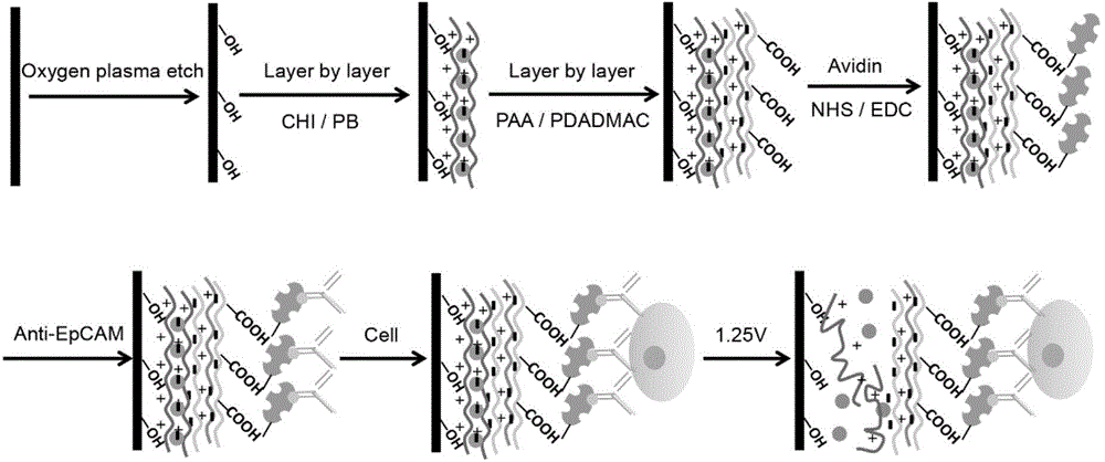
[0091] The preparation process and working principle of the chip body are as follows: figure 1 Shown, its preparation process comprises the following steps:
[0092] (1) Use dichloromethane, acetone, methanol and deionized water to ultrasonically clean the ITO conductive glass for 15 minutes, then use plasma etching (Harrick PCD32G) to treat the ITO conductive glass for 5 minutes, and put the treated ITO conductive glass into the pre-prepared Stand still 3min in the chitosan solution;
[0093] (2) According to the standard method of layer-by-layer self-assembly, soak the ITO conductive glass alternately in the chitosan solution and the Prussian blue nanoparticle solution for layer-by-layer self-assembly treatment. Wash with .0 deionized water for 3 minutes to form a micro-voltage response release layer (CHI / PB) on the surface of ITO conductive glass 27 ;
[0094] (3) According to the standard method of layer-by-layer self-...
Embodiment 2
[0098] Example 2 Preparation of Cell Sorting and Enrichment Device
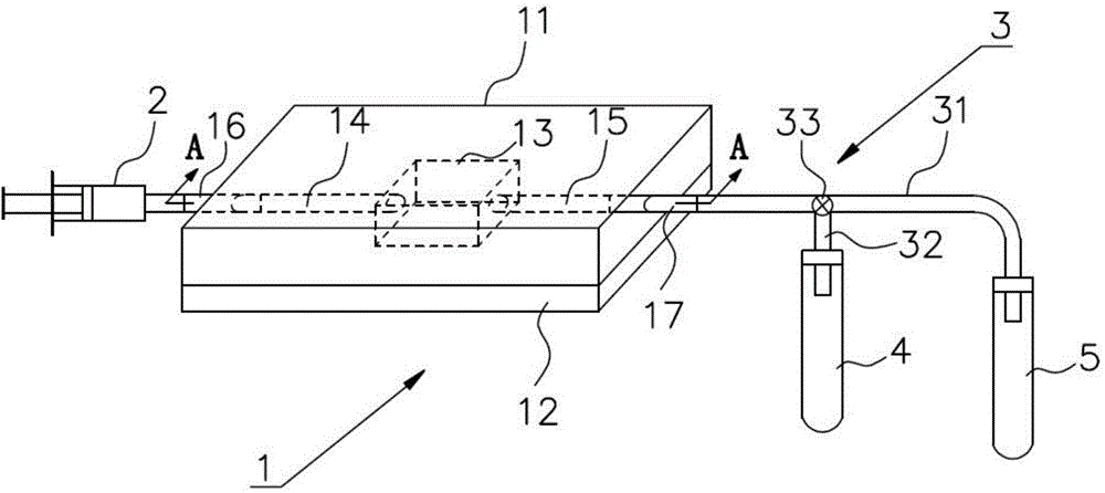
[0099] Such as Figure 2a As shown, a cell sorting and enrichment device in this embodiment includes a microfluidic chip 1, a micro-injection pump 2, a three-way tube 3, a waste liquid collection tube 4, a target cell collection tube 5, and an electrochemical workstation (Fig. omitted).
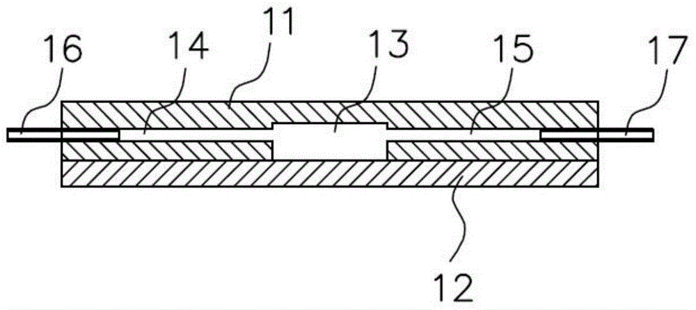
[0100] Depend on Figure 2a and 2b It can be seen that the microfluidic chip 1 includes a stacked and fixed chip body 12 (made by Example 1) and a cover 11. The cover 11 is provided with a groove 13, a sample injection channel 14 communicated with the groove 13, and a The sample outlet channel 15 , and the opening of the groove 13 faces the chip body 12 .
[0101] The cover body 11 is made of PDMS material, and it is convenient to set the groove 13 , the sample inlet channel 14 and the sample outlet channel 15 thereon. The fixing method of the cover 11 and the chip body 12 is as follows: when the cover 11 is relatively ...
Embodiment 3
[0108] Embodiment 3 morphology characterization and performance test
[0109] (1) Carry out morphology characterization to the product obtained in embodiment 1 step (2)
[0110] Figure 3a Shown is the appearance diagram of the corresponding product when n in the micro-voltage response release layer (CHI / PB)n is 0, 3, 6, 9, 12, 15, 18, 21, 24, and 27 respectively.
[0111] Use ellipsometry Puyi to measure the film thickness of products with different number of layers, the results are as follows Figure 3b shown.
[0112] Utilize the ultraviolet-visible spectrophotometer to detect the linear change of the absorption value at 700nm of the products with different treatment layers, the results are as follows Figure 3c shown.
[0113] Utilize the scanning electron microscope to obtain the product surface topography map of n=27, such as Figure 3d shown.
[0114] Utilize the atomic force microscope to obtain the product surface topography map of n=27, such as Figure 3e show...
PUM
| Property | Measurement | Unit |
|---|---|---|
| Concentration | aaaaa | aaaaa |
| Particle size | aaaaa | aaaaa |
Abstract
Description
Claims
Application Information
 - R&D
- Intellectual Property
- Life Sciences
- Materials
- Tech Scout
- Unparalleled Data Quality
- Higher Quality Content
- 60% Fewer Hallucinations
Browse by: Latest US Patents, China's latest patents, Technical Efficacy Thesaurus, Application Domain, Technology Topic, Popular Technical Reports.
© 2025 PatSnap. All rights reserved.Legal|Privacy policy|Modern Slavery Act Transparency Statement|Sitemap|About US| Contact US: help@patsnap.com


