
Power supply system and method for temperature measurement device of rotary kiln

A technology of power supply system and temperature measuring device, which is applied in the field of rotary kiln, and can solve the problems of impact on battery capacity and life, affecting temperature measurement in the kiln, and untimely battery replacement.

Active Publication Date: 2016-04-06
ZHONGYE-CHANGTIAN INT ENG CO LTD
View PDF10 Cites 6 Cited by
  • Summary
  • Abstract
  • Description
  • Claims
  • Application Information

AI Technical Summary

Problems solved by technology

[0003] In the process of realizing the present invention, the inventor found that the temperature measuring device is generally powered by batteries, but because sending and receiving wireless signals consumes more power, and the battery capacity is limited, and the capacity and life of the battery will be affected at high temperatures, so the rotary kiln After working for a period of time, the battery of the temperature measuring device needs to be replaced. However, at present, the replacement of the battery can only be carried out after the rotary kiln stops rotating. Affects the measurement of the temperature in the kiln

Method used


Image

  • Power supply system and method for temperature measurement device of rotary kiln
  • Power supply system and method for temperature measurement device of rotary kiln
  • Power supply system and method for temperature measurement device of rotary kiln

Examples


Embodiment Construction

[0044] Reference will now be made in detail to the exemplary embodiments, examples of which are illustrated in the accompanying drawings. When the following description refers to the accompanying drawings, the same numerals in different drawings refer to the same or similar elements unless otherwise indicated. The implementations described in the following exemplary examples do not represent all implementations consistent with the present invention. Rather, they are merely examples of apparatuses and methods consistent with aspects of the invention as recited in the appended claims.

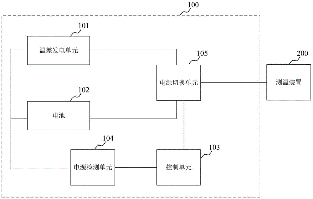
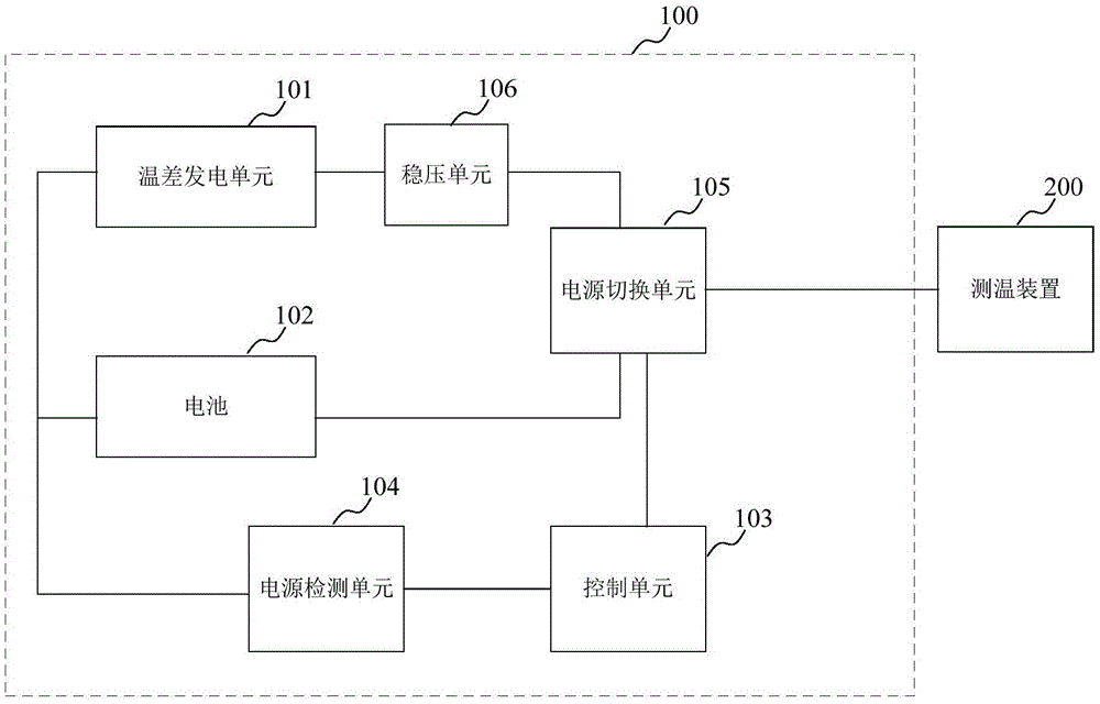
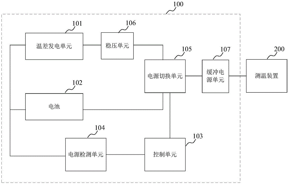
[0045] figure 1 It is a schematic diagram of a power supply system for a rotary kiln temperature measuring device according to an exemplary embodiment. The power supply system is arranged on the kiln body of the rotary kiln. see figure 1 As shown, the power supply system 100 may include a thermoelectric power generation unit 101 , a battery 102 , a control unit 103 , a power detection unit 10...


PUM


Abstract

The embodiment of the invention provides a power supply system and method for a temperature measurement device of a rotary kiln. The power supply system is arranged on a rotary kiln body and comprises a temperature difference power generation unit, a battery, a control unit, a power detection unit and a power switching unit, wherein the temperature difference power generation unit comprises a temperature difference semiconductor, a hot end of the temperature difference semiconductor is in close contact with the outer wall of the rotary kiln, a cold end of the temperature difference semiconductor is in close contact with a heat sink exposed in the air, the power detection unit is used for acquiring power generation voltage of the temperature difference power generation unit, the control unit is used for sending a switching signal to the power switching unit according to a relation of the power generation voltage of the temperature difference power generation unit and a threshold value, and the power switching unit is used for controlling a power supply part of the temperature measurement device to be switched between the battery and the temperature difference power generation unit according to the switching signal. By the power supply system, the service lifetime of the battery during power supply is prolonged, the problem of power supply instability probably existing in the temperature difference power generation unit is also solved, and finally, the purpose that stable power supply can be acquired by the temperature measurement device is achieved.

Description

technical field [0001] The invention relates to the technical field of rotary kilns, in particular to a power supply system and method for a temperature measuring device of a rotary kiln. Background technique [0002] Rotary kiln is a cylindrical high-temperature kiln placed on an incline and can rotate continuously. It is a thermal equipment for drying and roasting materials. It is widely used in non-ferrous smelting, iron and steel metallurgy, chemical industry, cement, alumina, building materials, refractory In the technological process of materials and other industries. The temperature in the rotary kiln will directly affect the roasting quality. In the prior art, the temperature measuring device can be installed on the kiln wall, and then the temperature data measured by the temperature measuring device can be transmitted to the outside by using wireless communication technology. [0003] In the process of realizing the present invention, the inventor found that the te...

Claims


Application Information

Patent Timeline
Patent Type & Authority Applications(China)
IPC IPC(8): H02J7/32H02N11/00
CPCH02J7/32H02N11/002
Inventor 曾小信邱立运
Owner ZHONGYE-CHANGTIAN INT ENG CO LTD
Learn More