Electric power controller for vehicle with stop start system
a technology of electric power controller and stop-start system, which is applied in the direction of engine starter, machine/engine, vehicle sub-unit features, etc., can solve the problems of electric voltage reduction of power capacitor, electric energy is decreased before and after the engine, etc., to suppress re-starting performance, prevent the electric voltage of power capacitor from being decreased, and suppress the effect of electric energy loss
- Summary
- Abstract
- Description
- Claims
- Application Information
AI Technical Summary
Benefits of technology
Problems solved by technology
Method used
Image
Examples
first embodiment
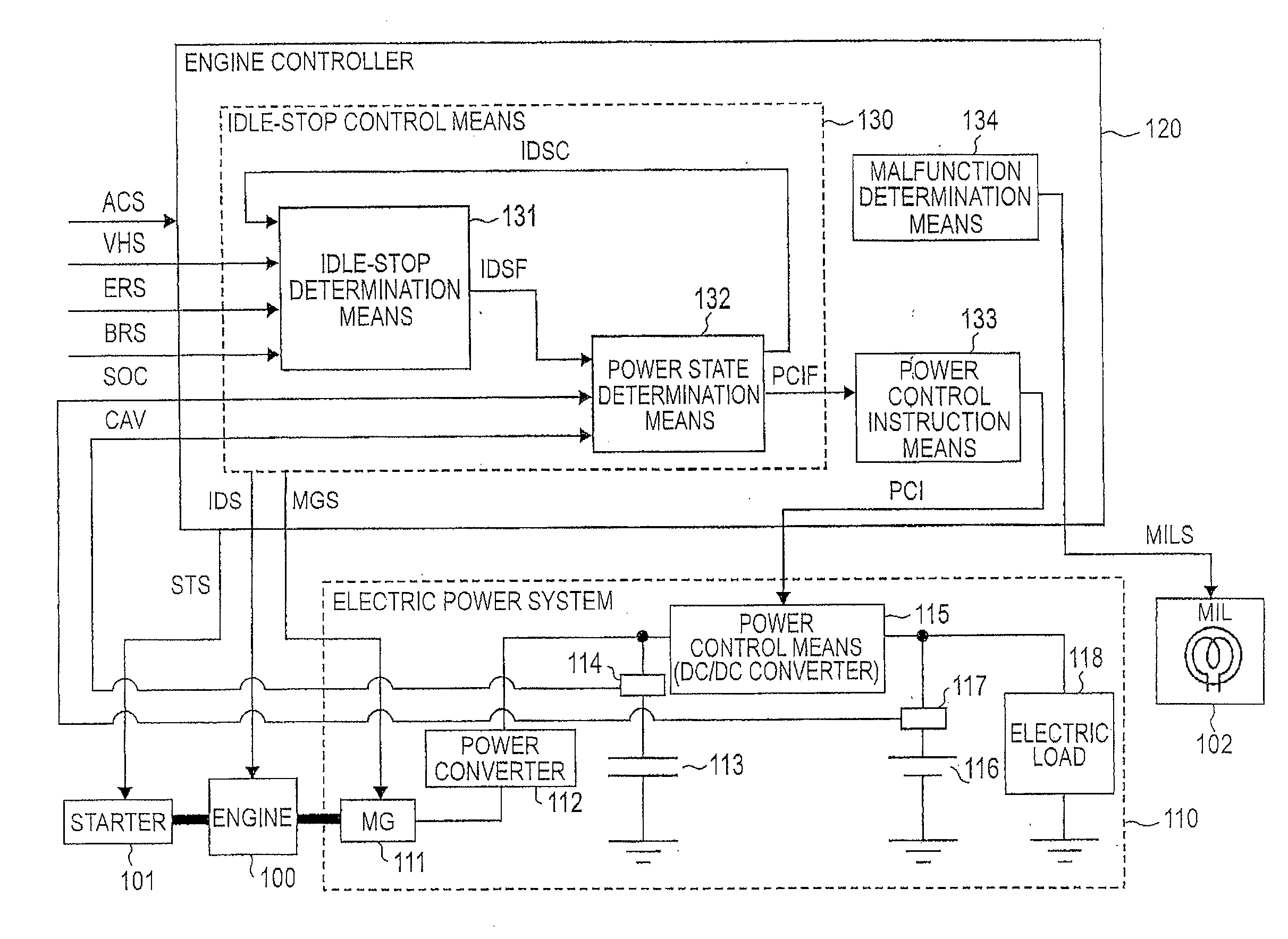
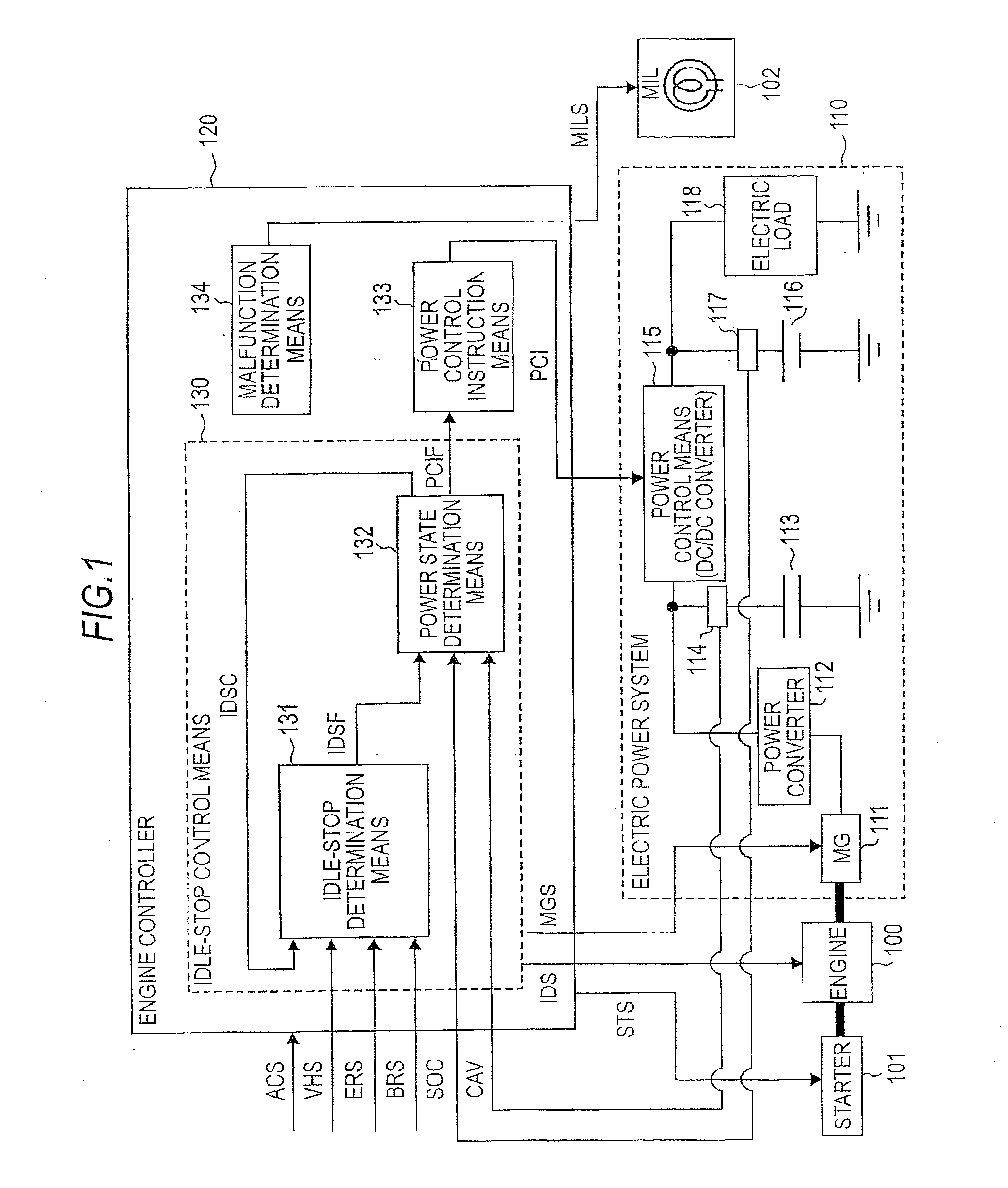
[0022]FIG. 1 is a block diagram illustrating an overall configuration of an electric power controller for a vehicle with stop-start system according to a first embodiment of the invention.
(1) Description of the Overall Configuration of the First Embodiment
[0023]Firstly, the overall configuration of the first embodiment will be described with reference to FIG. 1.
[0024]The electric power controller for the vehicle with stop-start system according to the first embodiment includes an engine 100, a starter 101, a malfunction indicating means 102, an electric power system 110, and an engine controller 120. The vehicle with stop-start system is automatically controlled to an idle-stop state according to an operating condition of the vehicle. Specifically, when the vehicle is in a temporary stop state, the vehicle is automatically controlled to the idle-stop state. The temporary stop of the vehicle may include, for example, a temporary stop during running of the vehicle, and may include a t...
second embodiment
[0103]FIG. 9 is a flowchart illustrating an electric power control operation in an electric power controller for a vehicle with stop-start system according to a second embodiment of the present invention. In the second embodiment, compared with the first embodiment, the flowchart illustrating the electric power control in FIG. 3 is changed into the flowchart shown in FIG. 9. The second embodiment is configured in the same way as in the first embodiment, other than this point.
[0104]In the flowchart shown in FIG. 9, compared with the flowchart in FIG. 3, step S303 is performed after the determination result of step S304 becomes “Yes”, and step S309 is changed into step S309a. Further, in the second embodiment, the power control means or DC / DC converter 115 stops the operation in step S303 when the idle-stop control means 130 idle-stops the engine 100, but since step S303 is performed when the determination result of step S304 becomes “Yes”, the operation is stopped when the state of c...
PUM
 Abstract
Description
Claims
Application Information
 - R&D
- Intellectual Property
- Life Sciences
- Materials
- Tech Scout
- Unparalleled Data Quality
- Higher Quality Content
- 60% Fewer Hallucinations
Browse by: Latest US Patents, China's latest patents, Technical Efficacy Thesaurus, Application Domain, Technology Topic, Popular Technical Reports.
© 2025 PatSnap. All rights reserved.Legal|Privacy policy|Modern Slavery Act Transparency Statement|Sitemap|About US| Contact US: help@patsnap.com


