A crankcase exhaust gas treatment system
An exhaust gas treatment and crankcase technology, applied in crankcase ventilation, engine components, machines/engines, etc., can solve the problems of slow combustion speed, increased fuel consumption, excessive exhaust emissions, etc., to achieve improved sensitivity, sufficient combustion, and reduced power insufficient effect
- Summary
- Abstract
- Description
- Claims
- Application Information
AI Technical Summary
Problems solved by technology
Method used
Image

Examples
Embodiment 1
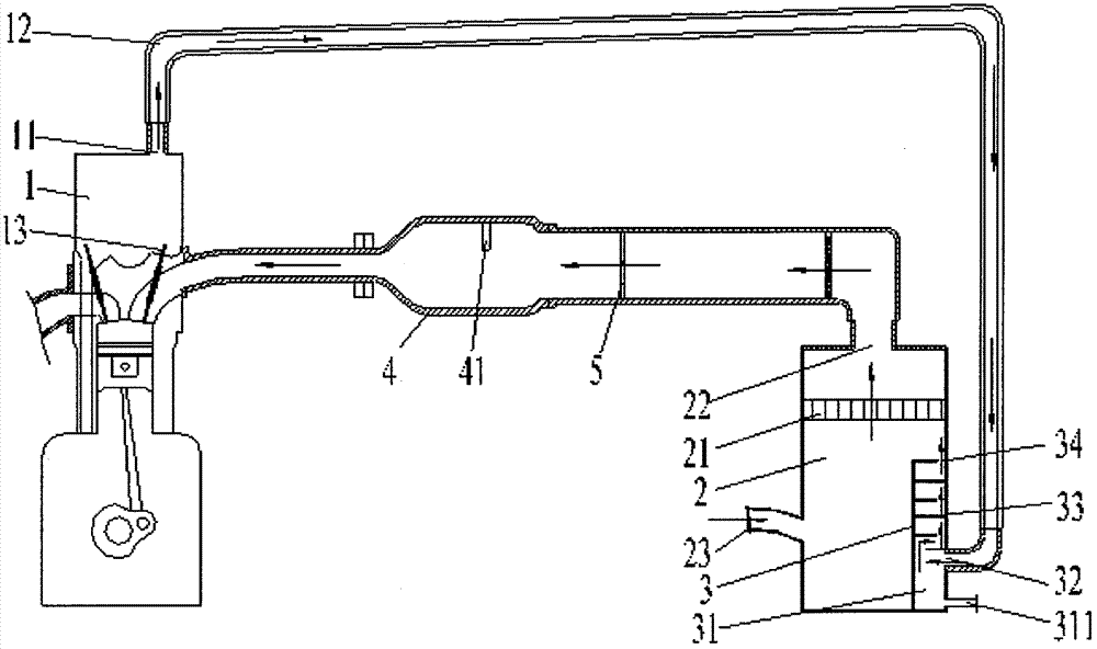
[0013] Embodiment 1: as figure 2 As shown, the present invention provides a crankcase exhaust gas treatment system, comprising a crankcase valve chamber cover 1, a vent 11 located on the crankcase valve chamber cover, an air filter 2, an air filter located on the air filter The air filter element 21 in the cleaner 2 and the oil-water separator 3 located at the bottom of the air filter 2; the oil-water separator 3 includes an exhaust gas inlet 32, a combustible mixture outlet 34, a condensing device 33 located inside the oil-water separator 3 and The oil-water settling chamber 31 is located at the bottom of the oil-water separator 3, the waste gas inlet 32 is located above the oil-water settling chamber 31, and the bottom of the oil-water settling chamber 31 is provided with a sewage outlet 311; a ventilation bellows 12 is provided between the waste gas inlet 32 and the vent 11; The crankcase exhaust gas passes through the ventilation bellows 12 and the oil-water separator...
Embodiment 2
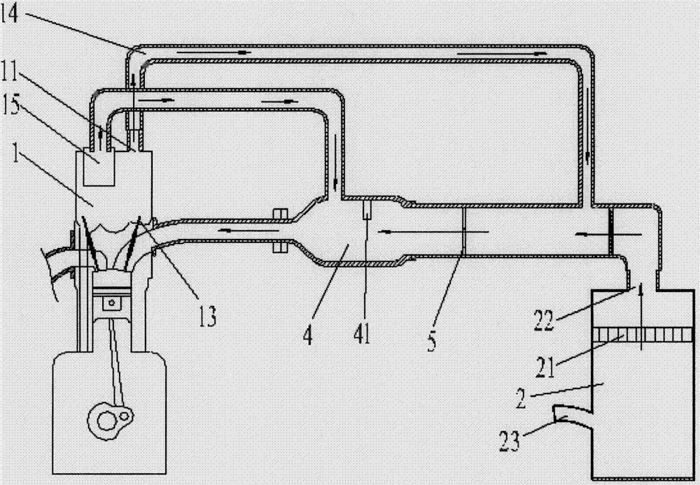
[0015] Embodiment 2: In order to ensure that the combustible mixture entering the intake manifold 4 is clean and dry, or not polluted by the dusty air entering from the air inlet 23, a technical feature is added on the basis of the above implementation 1: the combustible mixture passes through The gas at the outlet 34 enters the intake manifold 4 after being filtered by the air filter element 21 . It further ensures the cleanness and dryness of the combustible mixed gas entering the intake combustion system.
[0016] If the sludge is formed at the throttle valve, due to the mechanical switch of the throttle valve 5, a sludge step is formed on the outer edge of the throttle valve 5. When the vehicle is running at a low speed, due to the small opening of the throttle valve 5, the intake air is hindered by the sludge step , so that the intake air volume does not match the opening of the throttle valve 5, resulting in insufficient intake air volume, resulting in too rich combustib...
Embodiment 3
[0017] Embodiment 3: Different from the above-mentioned embodiments, the length of the ventilation bellows in this embodiment is 50-80 cm; and the ventilation bellows 12 are arranged obliquely upward from the vent 11 along the crankcase exhaust gas outflow direction. During the process of exhaust gas flowing in the bellows, relatively stable engine oil gas can be attached to the bellows to become oil liquid. Using the bellows as the ventilation bellows increases the area in contact with the exhaust gas, and the exhaust gas flows in the bellows due to Due to the specific shape of the bellows, many air swirl pockets are formed, which makes the effect of separating the oil liquid from the exhaust gas obvious. In order to allow the separated engine oil liquid to flow back into the crankcase, the present embodiment defines that the ventilation bellows 12 are arranged obliquely upwards from the vent 11 along the exhaust gas flow direction of the crankcase, that is, the position of th...
PUM
 Abstract
Description
Claims
Application Information
 - Generate Ideas
- Intellectual Property
- Life Sciences
- Materials
- Tech Scout
- Unparalleled Data Quality
- Higher Quality Content
- 60% Fewer Hallucinations
Browse by: Latest US Patents, China's latest patents, Technical Efficacy Thesaurus, Application Domain, Technology Topic, Popular Technical Reports.
© 2025 PatSnap. All rights reserved.Legal|Privacy policy|Modern Slavery Act Transparency Statement|Sitemap|About US| Contact US: help@patsnap.com