Thermal tube type vacuum drier capable of utilizing afterheat

A vacuum dryer and vacuum unit technology, applied in non-progressive dryers, dryers, drying solid materials, etc., can solve the problems of low heat energy use efficiency, small heat dissipation area, unutilized heat energy, etc. High cost performance, high heat conversion efficiency, and the effect of shortening drying time

Active Publication Date: 2016-03-23
常州奕诺梵节能科技有限公司
View PDF5 Cites 1 Cited by
  • Summary
  • Abstract
  • Description
  • Claims
  • Application Information

AI Technical Summary

Problems solved by technology

[0002] Nowadays, in the processing and production fields of grain, food, chemical industry, medicine, agricultural and sideline products, pasture, etc., it is necessary to heat and vacuum dry the materials; the heat exchange of the rotary vacuum drying equipment on the market now mostly uses row-pipe heat dissipation, Interlayer heating is used for heat exchange and heat dissipation, but their radiators are large in size, small in heat dissipation area, and low in efficiency of heat energy use
Wet materials often form agglomerates during the vacuum drying process, resulting in uneven drying of the wet materials, which affects the drying quality of the materials. The materials cannot be cooled during the vacuum drying process. Cooling in the normal pressure environment will cause the materials to return to moisture. Preservation, the heat energy released when the high-temperature material after vacuum drying is cooled cannot be used

Method used


Image

  • Thermal tube type vacuum drier capable of utilizing afterheat
  • Thermal tube type vacuum drier capable of utilizing afterheat
  • Thermal tube type vacuum drier capable of utilizing afterheat

Examples


Embodiment 1

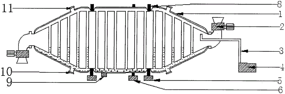
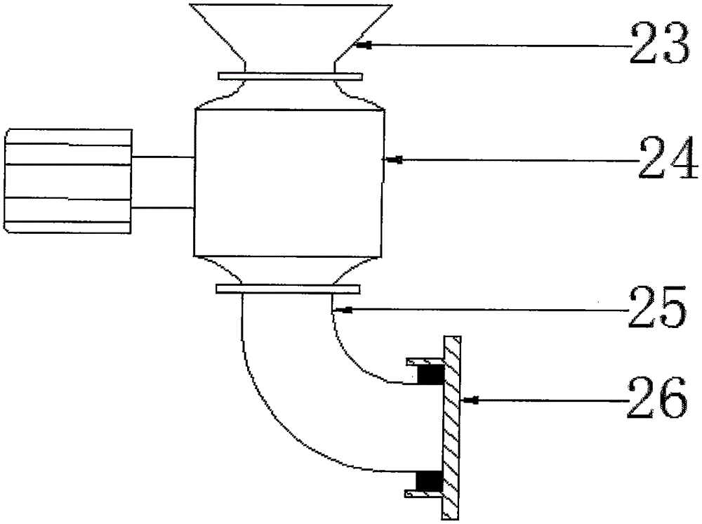
[0059] like figure 1 Shown is a heat pipe vacuum dryer (Type A) that can utilize waste heat, which consists of a heat pipe drying chamber (1) that can utilize waste heat, a vacuum feeding and discharging device (2), an air duct (3), and a vacuum unit (4) , a bracket (5), a driving device (6), a track (8) and a heating device (9).

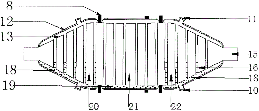
[0060] like figure 1 , figure 2 The shown heat pipe drying chamber (1) that can utilize waste heat is composed of an outer shell (12), an inner chamber (13), a heat-conducting working medium (19) and a heat-conducting medium (18).

[0061] The inner bin (13) is composed of a bin body, a cooling standpipe (16) and spiral blades.

[0062] The interior of the inner chamber (13) is divided into a preheating section (22), a drying section (21) and a cooling section (20).

[0063] The outer casing (12) is respectively installed on the preheating section (22), the drying section (21) and the cooling section (20) of the inner chamber (13).

[0064] Th...

Embodiment 2

[0118] Such as Figure 4 Shown is a heat pipe vacuum dryer (Type B) that can utilize waste heat, which consists of a heat pipe drying chamber (1) that can utilize waste heat, a vacuum feeding and discharging device (2), an air duct (3), and a vacuum unit (4) , a support (5), a driving device (6), a track (8), and a heating device (9).

[0119] Such as Figure 4 A kind of heat pipe vacuum dryer (B type) that can utilize waste heat shown is the same as the combined structure of the heat pipe vacuum dryer (A type) that can utilize waste heat introduced in embodiment 1 and will not be repeated.

[0120] Such as Figure 5 The shown heat pipe drying chamber (1) that can utilize waste heat is composed of an outer shell (12), an inner chamber (13), a heat-conducting working medium (19) and a heat-conducting medium (18).

[0121] The interior of the inner warehouse (13) is divided into a drying section (21) and a cooling section (20); the drying section (21) and the cooling section ...


PUM


Abstract

The invention discloses a thermal tube type vacuum drier capable of utilizing afterheat. The thermal tube type vacuum drier consists of a thermal tube drying cabin capable of utilizing afterheat, an air guide pipe, a bracket, a vacuum unit, a heating device, a driving device, rails and a vacuum charging and discharging device, wherein the rail on the thermal tube drying cabin capable of utilizing afterheat is mounted on the bracket; the driving device is used for driving the rail on an inner cabin; one end of the air guide pipe is connected to the vacuum unit after passing through the vacuum charging and discharging device; the other end of the air guide pipe is connected to the inside of the inner cabin; the inner cabin of the drying cabin adopts three-dimensional heat conduction by a cabin body and a cooling vertical tube, so the heat conduction speed and the heat exchange speed are increased; a cooling tube and a helical blade have a stirring function; no dead corner exists in material drying; the material drying time is shortened, so that the material can be dried uniformly; the material drying efficiency is improved; the material drying effect is optimized; the material can be cooled during a vacuum drying process; heat energy released in cooling of the material is also utilized, so continuous vacuum material drying can be realized.

Description

technical field [0001] The invention relates to a vacuum dryer, in particular to a heat pipe vacuum dryer capable of utilizing waste heat. Background technique [0002] Nowadays, in the processing and production fields of grain, food, chemical industry, medicine, agricultural and sideline products, pasture, etc., it is necessary to heat and vacuum dry the materials; the heat exchange of the rotary vacuum drying equipment on the market now mostly uses row-pipe heat dissipation, The interlayer heating method performs heat exchange and heat dissipation, but their radiators are large in size, small in heat dissipation area, and low in efficiency of heat energy use. Wet materials often form agglomerates during the vacuum drying process, resulting in uneven drying of the wet materials, which affects the drying quality of the materials. The materials cannot be cooled during the vacuum drying process. Cooling in the normal pressure environment will cause the materials to return to m...

Claims


Application Information

Patent Timeline
Patent Type & Authority Applications(China)
IPC IPC(8): F26B11/12F26B7/00F26B25/00
CPCF26B7/00F26B11/12F26B25/00
Inventor 张海娟
Owner 常州奕诺梵节能科技有限公司
Why Eureka
Try Eureka