Process for on-line cleaning to double rotational flow gas burner

A gas burner and double-swirl technology, applied in the boiler field, can solve the problems affecting the safe and stable operation of the boiler, the limitation of the continuous operation time of the boiler, and the easy damage of the gas side swirl sheet, so as to reduce the emission of blast furnace gas, reduce the operation and Maintenance cost and the effect of reducing the number of shutdowns

Active Publication Date: 2016-03-16
JIANGSU JIULIAN METALLURGY MACHINERY
View PDF6 Cites 5 Cited by
  • Summary
  • Abstract
  • Description
  • Claims
  • Application Information

AI Technical Summary

Problems solved by technology

Due to the relatively simple structure of this type of burner, the degree of mixing of combustible gas and air is high, the ignition is stable, the power is large, and the combustion efficiency is high. It is relatively fixed and cannot be adjusted by the user. Therefore, this type of burner is only suitable for burning relatively clean gas fuels; its fuel types mainly include: blast furnace gas, coke oven gas and converter gas
In actual use, we found that due to various factors, the above-mentioned fuels have the following two types of outstanding problems: one is that the swirl plate on the gas side is seriously blocked; Restrictions and reduction of boiler output will affect the safe and stable operation of the boiler in severe cases, causing many users to be forced to shut down frequently in a short period of time, requiring a lot of manual labor to enter the furnace to clean the burners. At the same time, due to severe corrosion, the service life of the burners is shortened. Need to replace the burner frequently, resulting in high cost of spare parts

Method used


Image

  • Process for on-line cleaning to double rotational flow gas burner
  • Process for on-line cleaning to double rotational flow gas burner
  • Process for on-line cleaning to double rotational flow gas burner

Examples


Embodiment Construction

[0040] The present invention will be further described below in conjunction with accompanying drawing, but not as limiting the present invention:

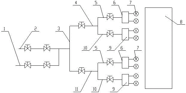
[0041]A process for online cleaning of double-swirl gas burners, including a gas branch pipe 1, an incoming branch pipe 2, and a furnace 8. The gas branch pipe 1 and the incoming branch pipe 2 are connected in parallel to the purge circuit main pipe 3, and the purge circuit main pipe 3 It is connected in two ways, one way is connected to the cut-off valve and then connected to the branch pipe 4 of the upper row of burner purge circuit, and the other way is connected to the stop valve and then connected to the branch pipe 11 of the lower row of burner purge circuit; the upper row of burner purge circuit The branch pipe 4 is connected to the cut-off valve and then connected in two ways, one of which is connected to the branch pipe 5 of the right half swirl sheet purge circuit of the burner, and the other end of the branch pipe 5 of th...


PUM


Abstract

The invention discloses a process for on-line cleaning to a double rotational flow gas burner. The process comprises the following steps: A), determining a purging medium; B), determining purging loops and the quantity thereof before the burner; C), distributing and determining the quantity of the purging branch pipe loops of a swirl plate spray nozzle set inside the burner; D), determining the quantity N of the purging branch pipes of a swirl plate spray nozzle of the burner according to the quantity N of swirl plates, and then accessing N spray nozzles, so as to form a spray nozzle set purging loop component; E), selecting the model of and making a swirl plate purging spray nozzle of the burner; F), determining the fixing way of the swirl plate purging spray nozzle of the burner and a pipeline; G), controlling and designing of the valve of a purging pipeline; and H), running test: 1, nitrogen purging; and 2, water purging. The process provided by the invention has a reasonable structure, can be used for on-line cleaning to the blockage of the swirl plates of the double rotational flow gas burner, can enable the continuous operating period of the burner to be prolonged greatly, and prolongs the service life of the double rotational flow gas burner; and on-line running and operation are simple, and system maintenance is small.

Description

technical field [0001] The invention belongs to the technical field of boilers, and in particular relates to an online cleaning process of a double swirl gas burner. Background technique [0002] At present, double swirl gas burners are widely used in full-fired gas boilers and mixed-fired gas boilers. Due to the relatively simple structure of this type of burner, the degree of mixing of combustible gas and air is high, the ignition is stable, the power is large, and the combustion efficiency is high. It is relatively fixed and cannot be adjusted by the user. Therefore, this type of burner is only suitable for burning relatively clean gas fuels; the main types of fuels are: blast furnace gas, coke oven gas and converter gas. In actual use, we found that due to various factors, the above-mentioned fuels have the following two types of outstanding problems: one is that the swirl plate on the gas side is seriously blocked; Restriction, boiler output decline, in serious cases ...

Claims


Application Information

Patent Timeline
Patent Type & Authority Applications(China)
IPC IPC(8): F23D14/50
CPCF23D14/50
Inventor 王仲明陈纪龙
Owner JIANGSU JIULIAN METALLURGY MACHINERY
Why Eureka
Try Eureka