
Machining device for matt cable

A processing equipment and cable technology, which is applied in the field of matte cable processing equipment, can solve problems such as cable swaying and shaking, achieve the effects of eliminating specular reflection, meeting the requirements of power transmission, low corona and no decline in electromagnetic interference performance

Active Publication Date: 2016-03-09
蚌埠格识知识产权运营有限公司
View PDF7 Cites 3 Cited by
  • Summary
  • Abstract
  • Description
  • Claims
  • Application Information

AI Technical Summary

Problems solved by technology

[0004] Based on the technical problems in the above-mentioned background technology, the present invention proposes a matt cable processing equipment to solve the problem that the cable is swaying and shaking during the transmission process due to the injection force

Method used


Image

  • Machining device for matt cable

Examples


Embodiment Construction

[0014] Below, the technical solution of the present invention will be described in detail through specific examples.

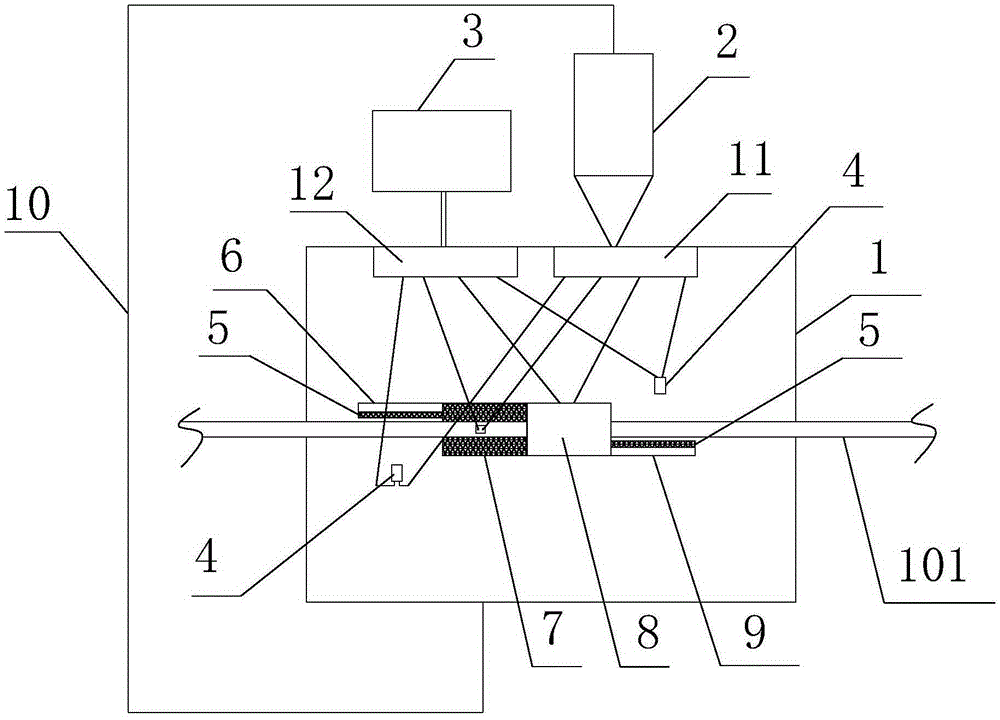
[0015] like figure 1 as shown, figure 1 It is a structural schematic diagram of a matt cable processing equipment proposed by the present invention.

[0016] refer to figure 1 , a kind of matte cable processing equipment that the embodiment of the present invention proposes, comprises: sandblasting box 1, centrifuge chamber 2, high pressure air source 3 and spray gun 4, wherein: sandblasting box 1 is provided with sand guiding pipe 11 and high pressure The air pipe 12; the centrifugal chamber 2 is set above the sandblasting box 1 and communicated with the sand guide pipe 11; the high-pressure air source 3 communicates with the high-pressure air pipe 12; the spray gun 4 is equipped with two inlets, one of which is connected with the sand guide pipe 11 , and the other is connected with the high-pressure gas pipe 12.

[0017] Both sides of the sandblasting bo...


PUM


Abstract

The invention discloses a machining device for a matt cable. The machining device comprises a sand blasting box, a centrifugal chamber and a high-pressure gas source. A sand guide pipe and a high-pressure gas pipe are arranged in the sand blasting box. The centrifugal chamber is arranged above the sand blasting box and communicated with the sand guide pipe. The high-pressure gas source is communicated with the high-pressure gas pipe. A cable inlet and a cable outlet are formed in the two sides of the sand blasting box respectively. Multiple baffles are arranged at the portion, between the cable inlet and the cable outlet, in the sand blasting box and distributed criss-cross in the cable conveying direction. One side of each baffle is provided with at least one spray gun, spray openings of the spray guns face the baffle faces, close to the conveyed cable, of the baffles, gaps allowing the cable to pass are reserved between the spray guns and the baffle faces of the baffles, each spray gun is provided with two inlets, one inlet of each spray gun is connected with the sand guide pipe, and the other inlet of each spray gun is connected with the high-pressure gas pipe. By the adoption of the machining device, the baffles are arranged criss-cross in the cable conveying direction, so that the situation that the cable swings and shakes due to blasting force in the sand blasting process, the sand blasting face is uneven, and conveyance is unstable is avoided.

Description

technical field [0001] The invention relates to the technical field of cable processing, in particular to a processing equipment for matte cables. Background technique [0002] With the surge of power transmission capacity, the coverage of power grids and lines is denser, and the impact of light pollution on densely populated areas and light-sensitive places cannot be ignored. For example: the overhead cables laid near the airport will affect the pilot's sight when the light is strong, and it will pose a serious threat to aviation safety, especially the opening of low-altitude areas. However, the surfaces of the cables in the prior art are all very bright, forming specular reflections, causing light pollution, and posing potential safety hazards. Therefore, it is necessary to treat the surface of the cable to reduce the light reflection on the surface of the cable. [0003] For example, a matt cable processing method and equipment proposed in Patent No. 201110104422.X uses...

Claims


Application Information

Patent Timeline
Patent Type & Authority Applications(China)
IPC IPC(8): B24C3/12B24C3/32B24C9/00
CPCB24C3/12B24C3/32B24C9/00
Inventor 谢安全黄承大
Owner 蚌埠格识知识产权运营有限公司
Learn More