A connection method and structure of a variable cross-section continuous rigid frame aqueduct

A connection method and variable section technology, applied in water conservancy projects, artificial waterways, buildings, etc., can solve problems such as stress concentration, cracking of construction joints, affecting the durability of aqueducts, etc., to reduce stress concentration, reduce connection stress, and strong waterproof ability. Effect

Active Publication Date: 2017-06-16
GUIZHOU SURVEY & DESIGN RES INST FOR WATER RESOURCES & HYDROPOWER
View PDF6 Cites 0 Cited by
  • Summary
  • Abstract
  • Description
  • Claims
  • Application Information

AI Technical Summary

Problems solved by technology

[0004] The single-chamber box girder and the double-chamber box girder of the existing continuous rigid frame aqueduct are directly connected. Since the cross-sectional shapes of the single-chamber box girder and the double-chamber box girder are different, a construction joint with a sudden change in section will inevitably appear at the connection point. , due to the sudden change of section at the construction joint will cause stress concentration, there are hidden dangers in the construction quality, due to the large expansion and contraction of the continuous rigid frame aqueduct, and the water body in the aqueduct body will gradually cause erosion and damage to the structural concrete and steel bars, eventually leading to cracking of the construction joint , which seriously affects the durability of the aqueduct, and even affects the safety of the structure
The direct connection between single-chamber box girder and double-chamber box girder in most existing continuous rigid-frame aqueducts cannot ensure the service life and structural safety of continuous rigid-frame aqueducts

Method used


Image

  • A connection method and structure of a variable cross-section continuous rigid frame aqueduct
  • A connection method and structure of a variable cross-section continuous rigid frame aqueduct
  • A connection method and structure of a variable cross-section continuous rigid frame aqueduct

Examples


Embodiment

[0033] Implementation steps of the present invention are as follows:

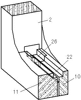
[0034] First complete the construction of the entire single-hole aqueduct and double-hole aqueduct bottom plate of the aqueduct. When the single-hole aqueduct and double-hole aqueduct bottom plate are about to close together, complete the transition groove bottom plate at the closing dragon mouth and let it stand for 30 days. Then complete the construction of the middle plate, seal and cushion on the bottom plate of the transition tank, and reserve space for the water-stop structure of the transition tank section; use modified epoxy resin adhesive to closely paste the stainless steel water-stop end on the water-stop belt reserved Notch and web junction area; during construction, such as image 3 As shown, the stainless steel water stop is bonded to the junction area between the notch and the web of the transition groove first, and then the U-shaped GB composite rubber water stop is installed. In order to cl...


PUM


Abstract

The invention discloses a connection method and structure of a variable section continuous rigid structure aqueduct. The method is to set a transition groove between the single-hole aqueduct and the double-hole aqueduct, and connect two single-hole aqueducts and double-hole aqueducts with different cross-sections smoothly through the transition groove, avoiding the connection between the single-hole aqueduct and the double-hole aqueduct. At the same time, a water stop device is installed on the bottom plate of the transition tank to prevent the water at the connection from gradually infiltrating and eroding the bottom plate of the transition tank. The invention solves the structural mutation of the existing connection structure caused by the connection of the single-hole aqueduct and the double-hole aqueduct by adding a transition groove at the connection of the single-hole aqueduct and the double-hole aqueduct, and slows down the connection stress. At the same time, the water stop device is used to prevent the water at the connection from gradually infiltrating and eroding the bottom plate of the transition tank, which will cause erosion and damage to the structural concrete and steel bars, and eventually lead to the cracking of the construction joints, which seriously affects the durability of the aqueduct and even affects the safety of the structure. .

Description

technical field [0001] The invention relates to a connection method and structure of a variable cross-section continuous rigid frame aqueduct, which belongs to the technical field of aqueducts in water conservancy projects. [0002] technical background [0003] With the rapid development of water conservancy projects in our country, the application of continuous rigid frame aqueducts with large spans and drainages is becoming more and more extensive. The bottom surface of the continuous rigid frame aqueduct with large span is usually arched, so the vault part is usually composed of a single-chamber box girder, and the double-chamber box girder is usually used near the arch end, so there must be a single-chamber box girder and a double-chamber box girder. Connection problem of box girder. [0004] The single-chamber box girder and the double-chamber box girder of the existing continuous rigid frame aqueduct are directly connected. Since the cross-sectional shapes of the sing...

Claims


Application Information

Patent Timeline
Patent Type & Authority Patents(China)
IPC IPC(8): E02B5/00
Inventor 徐江向国兴蒙进陈军罗代明罗亚松杨元红文明贡吴开昕欧波王家玉邵红艳
Owner GUIZHOU SURVEY & DESIGN RES INST FOR WATER RESOURCES & HYDROPOWER
Why Eureka
Try Eureka