
Preparation method for NiFe2O4@alpha-Fe micro nanometer composite material of core-shell structure

A composite material and core-shell structure technology, applied in the direction of nanotechnology, can solve the problems of easy oxidation, narrow absorption frequency band, poor matching performance, etc., and achieve the effects of easy acquisition, low preparation cost, and improved microwave absorption capacity

Active Publication Date: 2016-01-27
PLA SECOND ARTILLERY ENGINEERING UNIVERSITY
View PDF6 Cites 8 Cited by
  • Summary
  • Abstract
  • Description
  • Claims
  • Application Information

AI Technical Summary

Problems solved by technology

However, it has disadvantages such as narrow absorption frequency band, poor matching performance, and easy oxidation, and its application range is limited to a certain extent.

Method used


Image

  • Preparation method for NiFe2O4@alpha-Fe micro nanometer composite material of core-shell structure
  • Preparation method for NiFe2O4@alpha-Fe micro nanometer composite material of core-shell structure
  • Preparation method for NiFe2O4@alpha-Fe micro nanometer composite material of core-shell structure

Examples


Embodiment 1

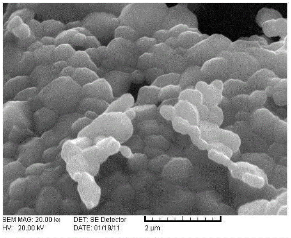
[0032] Step 1: Add 10g of purchased NiFe 2 o 4 powder and 15ml iron pentacarbonyl [Fe(CO) 5 ] into the reactor and the evaporator respectively;

[0033] Step 2: Switch on N 2 , blow out all the air in the pipeline, turn off the gas source, and close the valve between the reactor and the evaporator at the same time; 2 o 4 and Fe(CO) 5 Open the valve between the reactor and the evaporator when heating to 210°C and 80°C;

[0034] Step 3: Fe(CO) 5 Steam was blown into the reactor, and the stirring speed was 200r / min. N 2 The flow rate is controlled by a gas flow meter; Fe(CO) 5 Heated by a digital display constant temperature oil bath, gaseous Fe(CO) 5 The pipeline before entering the reactor is covered with a layer of insulation jacket to prevent the gaseous Fe(CO) 5 Condensation at low temperature, resulting in poor pipeline; Fe(CO) 5 The steam blowing time is 30min, and the final sample is in N 2 Cool and collect under protection, the obtained black powder is NiFe ...

Embodiment 2

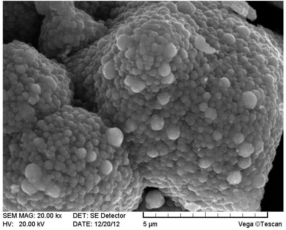
[0040] Step 1: 10g of prepared NiFe 2 o 4 powder and 15ml iron pentacarbonyl [Fe(CO) 5 ] into the reactor and the evaporator respectively;

[0041] Step 2: Switch on N 2 , Blow out all the air in the pipeline, turn off the air source, and close the valve between the reactor and the evaporator at the same time. NiFe 2 o 4 and Fe(CO) 5 Open the valve between the reactor and the evaporator when heating to 250°C and 80°C;

[0042] Step 3: Fe(CO) 5 The steam is blown into the reactor, and the stirring speed is 180r / min; N 2 The flow rate is controlled by a gas flow meter; Fe(CO) 5 Heated by a digital display constant temperature oil bath, gaseous Fe(CO) 5 The pipeline before entering the reactor is covered with a layer of insulation jacket to prevent the gaseous Fe(CO) 5 Condensation at low temperature, causing pipeline blockage. Fe(CO) 5 The steam blowing time is 30min, and the final sample is in N 2 Cool and collect under protection, the obtained black powder is NiF...


PUM

PropertyMeasurementUnit
particle diameteraaaaaaaaaa
sizeaaaaaaaaaa
thicknessaaaaaaaaaa

Abstract

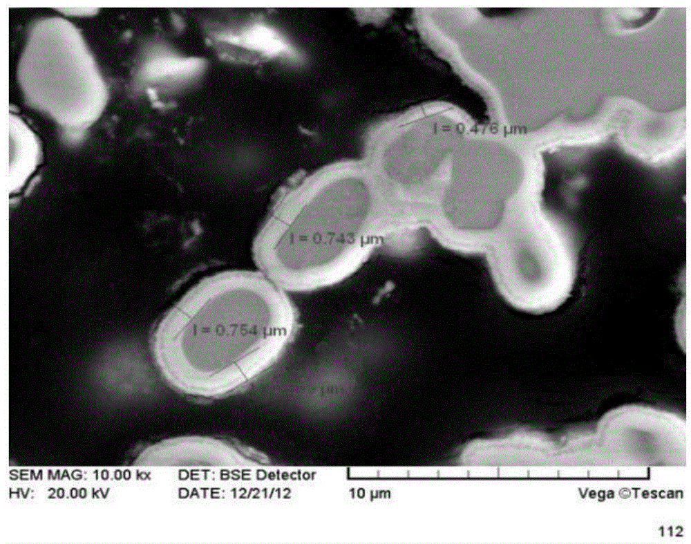
The invention relates to a preparation method for a NiFe2O4@alpha-Fe micro nanometer composite material of a core-shell structure through organic carbonyl based ferrous metal gas phase decomposition and deposition. The preparation method includes the steps that NiFe2O4 powder is put into a reactor, inert shielding gas is introduced, and heating is carried out slowly to make temperature rise; at the atmosphere of the shielding gas, Fe(CO)5 steam is introduced, decomposition deposition and reflux condensation are carried out in the reactor; after the reaction time is due, the shielding gas continues to be introduced; after the temperature of the device is decreased to the room temperature, the obtained powder is taken out. The NiFe2O4@alpha-Fe micro nanometer composite material powder of the core-shell structure can be obtained through one step, and has a large specific surface area. The form of the core-shell structure, the thickness of a shell layer and the reflection rate can be effectively adjusted by adjusting the reaction time and the deposition temperature. The preparation process is simple, products can be obtained easily, synthesis equipment is easy and convenient to operate, and the preparation cost is lower. The preparation method for the NiFe2O4@alpha-Fe micro nanometer composite material of the core-shell structure has potential application value in the fields such as electromagnetic wave absorption and shielding.

Description

technical field [0001] The invention belongs to the technical field of nanocomposite materials, and in particular relates to a method for preparing NiFe by vapor phase decomposition and deposition of organic carbonyl iron metal 2 0 4 Method for α-Fe core-shell structure micro-nanocomposites. Background technique [0002] Nowadays, with the rapid development of the electronic industry, electromagnetic radiation has become a new kind of environmental pollution, and its interference to various electronic equipment and harm to human health have gradually attracted widespread attention of researchers. At present, the anti-interference and protection methods mainly adopt electromagnetic shielding and anti-electromagnetic interference technology, which makes the research on wave-absorbing materials a hot issue. In the basic research of microwave-absorbing materials, the development of high-performance microwave-absorbing agents is the core technology of microwave-absorbing materi...

Claims


Application Information

Patent Timeline
Patent Type & Authority Applications(China)
IPC IPC(8): B22F9/28B22F1/02B82Y40/00
Inventor 刘祥萱刘渊刘鑫王煊军
Owner PLA SECOND ARTILLERY ENGINEERING UNIVERSITY
Learn More