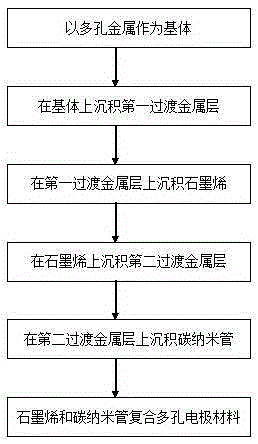
Preparing method for graphene and carbon nano tube composite porous electrode material
A carbon nanotube composite, porous electrode technology, applied in metal material coating process, superimposed layer plating, coating and other directions, can solve problems such as increasing nucleation density, rough surface of foamed nickel skeleton, and increasing electrode internal resistance. , to achieve the effect of elimination selectivity, high specific surface area and high catalytic activity
- Summary
- Abstract
- Description
- Claims
- Application Information
AI Technical Summary
Problems solved by technology
Method used
Image
Examples
Embodiment 1
[0028] Using nickel foam as the substrate, the selected nickel foam has an average pore diameter of 100 μm and a thickness of 0.3 mm. Cu is deposited on the surface of the substrate as the first transition metal layer using vacuum magnetron sputtering technology. The working parameters are: vacuum chamber background Vacuum≤5×10 -2Pa, the pressure in the vacuum chamber during sputtering coating is ≤1Pa, the target power density applied per decimeter of target width is 0.1 kW to 1 kW, and the average thickness of the first transition metal layer is 5 nm. Put it in a vacuum furnace chamber, evacuate until the background vacuum inside the furnace chamber is less than or equal to 2Pa, then raise the temperature to 900°C, and at the same time pass in a mixture of hydrogen and argon, keep it warm for 13 minutes, continue to heat up to 1040°C, and then pass in benzene The gas is reacted, and the reaction time is 0.5 minutes. After the reaction, stop feeding benzene gas, and cool to ro...
Embodiment 2
[0031] Using foamed aluminum as the substrate, the selected foamed aluminum has an average pore diameter of 400 μm and a thickness of 0.8 mm. Cu-Ni alloy is deposited on the surface of the substrate as the first transition metal layer using vacuum magnetron sputtering technology. The working parameters are: vacuum Cavity background vacuum ≤5×10 -2 Pa, the pressure in the vacuum chamber during sputtering coating is ≤1Pa, the target power density applied per decimeter of target width is 0.1 kW to 1 kW, the average thickness of the first transition metal layer is 300nm, and Cu-Ni alloy will be deposited on the surface Place the aluminum foam in the vacuum furnace chamber, evacuate until the background vacuum inside the furnace chamber is ≤ 2Pa, then raise the temperature to 800°C, and at the same time pass in the mixed gas of hydrogen and argon, keep it warm for 20 minutes, continue to heat up to 975°C, and then Feed ethylene gas to react, and the reaction time is 12 minutes. Aft...
Embodiment 3
[0034] Using nickel-iron foam as the substrate, the selected nickel-iron foam has an average pore diameter of 500 μm and a thickness of 1.5 mm. Co-Ni alloy is deposited on the surface of the substrate as the first transition metal layer using vacuum magnetron sputtering technology. The working parameters are: : Vacuum cavity background vacuum ≤5×10 -2 Pa, the pressure in the vacuum chamber during sputtering coating is ≤1Pa, the target power density applied per decimeter target width is 0.1 kW to 1 kW, the average thickness of the first transition metal layer is 400nm, and the Co-Ni alloy will be deposited on the surface The foamed nickel iron is placed in the vacuum furnace cavity, evacuated until the background vacuum inside the furnace cavity is ≤2Pa, and then heated up to 850°C, and at the same time, a mixed gas of hydrogen and argon is introduced, kept for 30 minutes, and continued to heat up to 1000°C. Then feed methane gas to react, the reaction time is 20 minutes, stop ...
PUM
| Property | Measurement | Unit |
|---|---|---|
| thickness | aaaaa | aaaaa |
| thickness | aaaaa | aaaaa |
| thickness | aaaaa | aaaaa |
Abstract
Description
Claims
Application Information
 - R&D Engineer
- R&D Manager
- IP Professional
- Industry Leading Data Capabilities
- Powerful AI technology
- Patent DNA Extraction
Browse by: Latest US Patents, China's latest patents, Technical Efficacy Thesaurus, Application Domain, Technology Topic, Popular Technical Reports.
© 2024 PatSnap. All rights reserved.Legal|Privacy policy|Modern Slavery Act Transparency Statement|Sitemap|About US| Contact US: help@patsnap.com


