Fan rotating speed detection apparatus

A technology for detecting device and fan speed, which can be used in measurement devices, linear/angular velocity measurement, velocity/acceleration/shock measurement, etc., and can solve problems such as low program execution efficiency

Active Publication Date: 2016-01-13
GUANGDONG VTRON TECH CO LTD
View PDF7 Cites 3 Cited by
  • Summary
  • Abstract
  • Description
  • Claims
  • Application Information

AI Technical Summary

Problems solved by technology

[0003] Based on this, it is necessary to provide a fan speed detection device for the technical problem that the traditional technology is easy to consume the clock resources inside the controller and cause low program execution efficiency.

Method used


Image

  • Fan rotating speed detection apparatus
  • Fan rotating speed detection apparatus
  • Fan rotating speed detection apparatus

Examples


Embodiment Construction

[0010] The specific implementation of the fan rotation speed detection device provided by the present invention will be described in detail below with reference to the accompanying drawings.

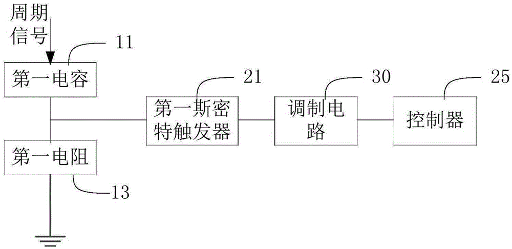
[0011] refer to figure 1 , figure 1 Shown is a schematic structural diagram of a fan speed detection device in an embodiment, including: a first capacitor 11, a first resistor 13, a first Schmitt trigger 21, a modulation circuit 30, and a controller 25;

[0012] One end of the first capacitor 11 is connected to the signal output end of the fan, the other end is connected to the input end of the first Schmitt trigger 21 and grounded through the first resistor 13, and the output end of the first Schmitt trigger 21 Connect the controller 25 through the modulation circuit 30;

[0013] The periodic signal output by the fan is converted into a pulse signal through the charging and discharging circuit composed of the first capacitor 11 and the first resistor 13 and output to the input termina...


PUM


Abstract

The invention relates to a fan rotating speed detection apparatus. The apparatus comprises a first capacitor, a first resistor, a first Schmitt trigger, a modulation circuit and a controller. One end of the first capacitor is connected to a signal output end of a fan, and the other end of the capacitor is connected to the input end of the first Schmitt trigger and is connected to the ground through the first resistor. The output end of the first Schmitt trigger is connected to the controller through the modulation circuit. A periodic signal output from the fan is converted into a pulse signal through a charge and discharge loop, the pulse signal is then output to the input end of the first Schmitt trigger, the first Schmitt trigger shapes the pulse signal into a rectangular wave signal, the modulation circuit modulates the rectangular wave signal and a reference voltage of the modulation circuit, then a voltage signal is obtained and input to the controller, the controller samples the voltage signal and a corresponding voltage value is obtained, and therefore the rotating speed of the fan is obtained. The apparatus can provides the program execution efficiency of the controller, and the detection cost for the rotating speed of a fan is reduced.

Description

technical field [0001] The invention relates to the technical field of fan control, in particular to a fan speed detection device. Background technique [0002] At present, fans are widely used in various product fields, especially in the heat dissipation design of the whole machine, the use of fans is even more essential. Usually, in order to ensure good heat dissipation performance and product reliability of the product, it is necessary to monitor the fan speed in real time. The traditional fan speed detection scheme is generally to directly input the periodic signal output by the fan into the controller, and use the above-mentioned controller to obtain the fan speed from the periodic signal, which easily consumes the clock resources inside the controller, resulting in low program execution efficiency. Contents of the invention [0003] Based on this, it is necessary to provide a fan speed detection device for the technical problem that the traditional technology is eas...

Claims


Application Information

Patent Timeline
Patent Type & Authority Applications(China)
IPC IPC(8): G01P3/481
Inventor 祝磊林文富
Owner GUANGDONG VTRON TECH CO LTD
Why Eureka
Try Eureka