A flue gas heat exchange device and flue gas treatment system

A flue gas treatment system and flue gas heat exchange technology, applied in the direction of indirect heat exchangers, heat exchanger types, climate sustainability, etc., can solve the problems of low waste heat utilization efficiency, air pollution, and low oil fume absorption efficiency, etc. To achieve the effect of improving utilization rate, low carbon energy saving, environmental pollution, and improving heat exchange efficiency

Active Publication Date: 2017-09-01
HENAN UNIV OF SCI & TECH
View PDF1 Cites 0 Cited by
  • Summary
  • Abstract
  • Description
  • Claims
  • Application Information

AI Technical Summary

Problems solved by technology

[0003] The above flue gas waste heat recovery device can recycle the waste heat carried in the flue gas, but it performs heat exchange through the heat collecting tube, and the waste heat utilization efficiency is low
In addition, when treating the flue gas containing oil fume, the absorption efficiency of oil fume is very low, most of the oil fume discharged into the atmosphere will pollute the air

Method used


Image

  • A flue gas heat exchange device and flue gas treatment system
  • A flue gas heat exchange device and flue gas treatment system
  • A flue gas heat exchange device and flue gas treatment system

Examples


Embodiment Construction

[0026] Embodiments of the flue gas treatment system of the present invention:

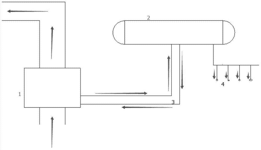
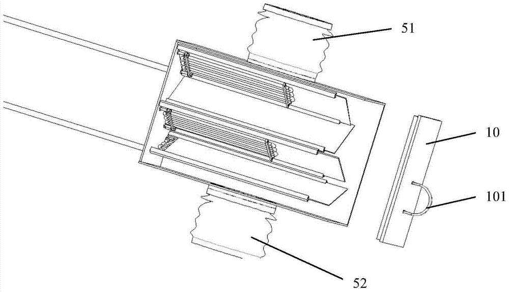
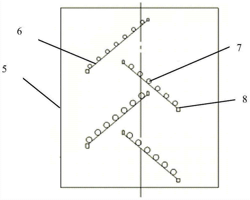
[0027] Such as Figure 1-7 As shown, the flue gas treatment system of this embodiment includes a flue gas heat exchange device 1 and a heat exchange fluid supply device connected thereto. The heat exchange fluid supply device includes a box body 5 for flue gas to pass through and a heat exchange tube 7 fixedly arranged in the box body. An air inlet pipe 51 is connected, the other end is an air outlet end, an air outlet is provided on the air outlet, an air outlet pipe 52 is connected to the air outlet, and a heat exchange plate 6 connected to the heat exchange tube is fixedly arranged in the box. The heat exchange plates are arranged staggeredly along the direction from the air inlet end to the air outlet end and form a serpentine flue gas channel in the box. The heat exchange plate is made of a material with good thermal conductivity, such as a metal material. In this embodiment, it is a copper ...


PUM


Abstract

The invention relates to an exhaust gas heat exchanging device and an exhaust gas treatment system and belongs to the technical field of waste heat utilization. The exhaust gas heat exchanging device comprises a box body allowing exhaust gas to pass through and heat exchanging pipes fixedly arranged in the box body. One end of the box body is a gas inlet end, and the other end of the box body is a gas outlet end. Heat exchanging plates which are in heat-conducting connection with the heat exchanging pipes are fixedly arranged in the box body. The multiple heat exchanging pipes are arranged on the heat exchanging plates. The heat exchanging plates are sequentially arranged in a staggered mode in the direction from the gas inlet end to the gas outlet end, and an S-shaped exhaust gas channel is formed in the box body. The exhaust gas heat exchanging device is capable of improving the heat exchanging efficiency of the heat exchanging treatment device and the exhaust gas; the afterheat in the exhaust gas is fully used. The retaining time of the exhaust gas in the box body is fully prolonged.

Description

technical field [0001] The invention relates to a flue gas heat exchange device and a flue gas treatment system, belonging to the technical field of waste heat utilization. Background technique [0002] With the continuous deepening of energy saving and emission reduction, higher requirements are put forward for energy utilization and exhaust gas emission in industrial production and family life. Reuse of waste heat is one of the effective ways to save energy. At present, there are relatively many waste heat recovery and utilization in industry, and the application is relatively mature, but the waste heat utilization in the civilian field and some small enterprises is relatively small. In the civilian field, there are studies on the use of heat pumps to recover waste heat, but the disadvantages of high cost of heat pump devices and difficult cleaning of evaporators have certain limitations in the process of popularization and use. In the prior art, when treating boiler flue...

Claims


Application Information

Patent Timeline
Patent Type & Authority Patents(China)
IPC IPC(8): F28D7/16F23J15/06
CPCY02E20/30
Inventor 兰维娟孙兵王学涛吴凤英周铭丽杜维新刘春梅李健
Owner HENAN UNIV OF SCI & TECH
Why Eureka
Try Eureka