
Pipe cutting machine capable of grinding edge while sucking dust

A pipe cutting machine and edge grinding technology, which is applied to machine tools suitable for grinding workpiece edges, parts of grinding machine tools, and grinding machines, can solve the problems of wasting manpower, high cutting defect rate, waste of material processing links, etc. achieve the effect of improving work efficiency

Inactive Publication Date: 2016-01-13
卢道东
View PDF0 Cites 2 Cited by
  • Summary
  • Abstract
  • Description
  • Claims
  • Application Information

AI Technical Summary

Problems solved by technology

[0002] After the steel pipe is cut, the inner edge of the steel pipe needs to be deburred, but the existing pipe cutting machine is cut, and the edge is manually grinded by a grinder, which wastes manpower and reduces work efficiency.
At the same time, the cut steel pipes are taken away manually for the next step of processing, which increases the labor force
In addition, when the pipe cutting machine cuts the steel pipe, it is easy to generate a large amount of waste chips. If the waste chips are not processed in time, it will affect the cutting effect of the steel pipe, resulting in a high rate of defective cutting and waste in the material processing link.

Method used


Image

  • Pipe cutting machine capable of grinding edge while sucking dust
  • Pipe cutting machine capable of grinding edge while sucking dust
  • Pipe cutting machine capable of grinding edge while sucking dust

Examples


Embodiment Construction

[0016] The present invention will be described in further detail below through specific implementation examples and in conjunction with the accompanying drawings.

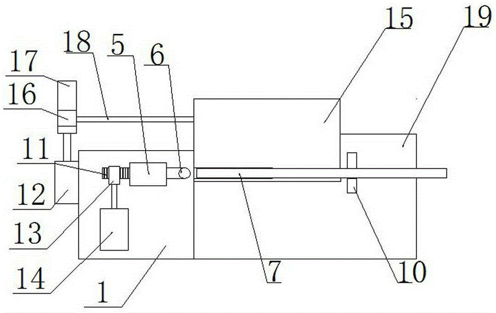
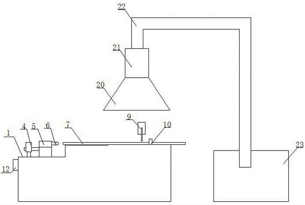
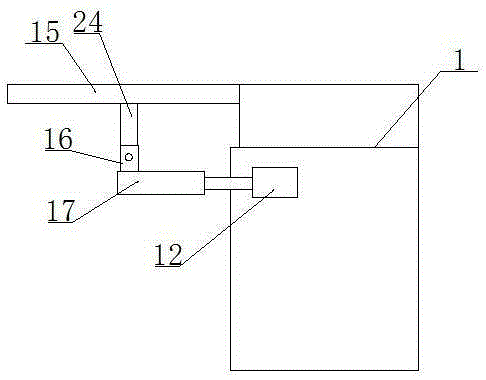
[0017] Figure 1-3 Shown is a pipe cutting machine capable of vacuuming and edging provided by the present invention, including: body edging surface 1, rotating motor 4, motor 5, sphere 6, steel pipe 7, cutting device 9, and electromagnet clamping block 10. Rack 11, cylinder 12, gear 13, rotating motor 14, rotating plate 15, roller teeth 16, bar teeth 17, transmission shaft 18, suction hood 20, fan 21, slag discharge pipe 22, collection box 23, Connecting rod 24 and body cutting surface 19. The working surface of the body includes a body edging surface 1 and a body cutting surface 19 higher than the body edging surface 1; a support seat is slidably provided on the body edging surface 1, and a motor 5 is provided on the support seat, and the motor output The shaft is connected with a sphere 6, and the outer surfac...


PUM


Abstract

The invention discloses a pipe cutting machine capable of grinding an edge while sucking dust. The pipe cutting machine comprises a machine body work surface. The machine body work surface comprises a machine body edge grinding surface and a machine body cutting surface higher than the machine body edge grinding surface. A supporting seat is arranged on the machine body edge grinding surface in a sliding mode and provided with a motor. An output shaft of the motor is connected with a sphere body, and abrasive materials are arranged on the outer surface of the sphere body. A fixing seat is arranged on the machine body edge grinding surface and provided with a rotary motor, and an output shaft of the rotary motor is connected with a gear. The gear is provided with a rack matched with the gear, and one end of the rack is connected with the supporting seat. An air cylinder is arranged on the lateral surface of a machine body, and an output shaft of the air cylinder is connected with a strip-shaped tooth. The strip-shaped tooth is provided with a roller tooth engaged with the strip-shaped tooth, and the roller tooth is provided with a transmission shaft driving a rotary plate to overturn. The pipe cutting machine capable of grinding the edge while sucking dust can improve work efficiency.

Description

technical field [0001] The invention relates to the technical field of pipe cutting machines, in particular to a pipe cutting machine capable of vacuuming and edging. Background technique [0002] After the steel pipe is cut, the inner edge of the steel pipe needs to be deburred, but the existing pipe cutting machine is all cut, and the edge is manually grinded by a grinder, which wastes manpower and reduces work efficiency. At the same time, the steel pipes after cutting are all taken away manually for the next step of processing, which increases the labor force. In addition, when the pipe cutting machine cuts the steel pipe, it is easy to generate a large amount of waste chips. If the waste chips are not processed in time, it will affect the cutting effect of the steel pipe, resulting in a high rate of cutting defects and waste in the material processing link. Contents of the invention [0003] The object of the present invention is to provide a pipe cutting machine cap...

Claims


Application Information

Patent Timeline
Patent Type & Authority Applications(China)
IPC IPC(8): B24B27/06B24B9/04B24B47/14B24B55/06
CPCB24B27/06B24B9/04B24B47/14B24B55/06
Inventor 卢道东
Owner 卢道东
Learn More