
Rotary plant growing apparatus

a technology of growing apparatus and rotating rod, which is applied in the field of rotary plant growing apparatus, can solve the problems of reducing the efficiency of the motor, affecting the growth rate of plants, so as to achieve easy leveling, simple and durable, and easy puncture

Inactive Publication Date: 2010-06-08
SOUVLOS ANGELO +2
View PDF8 Cites 27 Cited by
  • Summary
  • Abstract
  • Description
  • Claims
  • Application Information

AI Technical Summary

Benefits of technology

"The present invention provides an improved rotary plant growing apparatus that has several advantages. The apparatus has baskets for growing plants that are both removable and securely retained in place. The apparatus can be easily leveled on a surface and the mechanism driving rotation of the baskets is simple and durable. The apparatus may be easily assembled and disassembled. The baskets have easily puncturable apertures for providing liquid nutrients to the plants. The apparatus minimizes the loss of liquid nutrient for the plant during rotation. The apparatus is designed to at least partially immerse the basket in the nutrient liquid in the reservoir to nourish the plants."

Problems solved by technology

Unfortunately, the design of the apparatus of Leduc et al. described above has a number of deficiencies and disadvantages.
Therefore, there is a significant risk that liquid nutrient may leak out or escape from the basket during rotation and that the escaped liquid nutrient will not fall back into the reservoir.
Further, the chain and wheel combination connected to the motor used to drive the rotation of the cylindrical structure is subject to excessive wear, which reduces efficiency of the motor.
Unfortunately, as the pins lie freely in the slots, they are prone to slippage during rotation of the cylindrical structure, which may cause the baskets to wobble or to become detached from the rims.

Method used


Image

  • Rotary plant growing apparatus
  • Rotary plant growing apparatus
  • Rotary plant growing apparatus

Examples


Embodiment Construction

[0023]With reference to the annexed drawings the preferred embodiments of the present invention will be herein described for indicative purpose and by no means as of limitation.

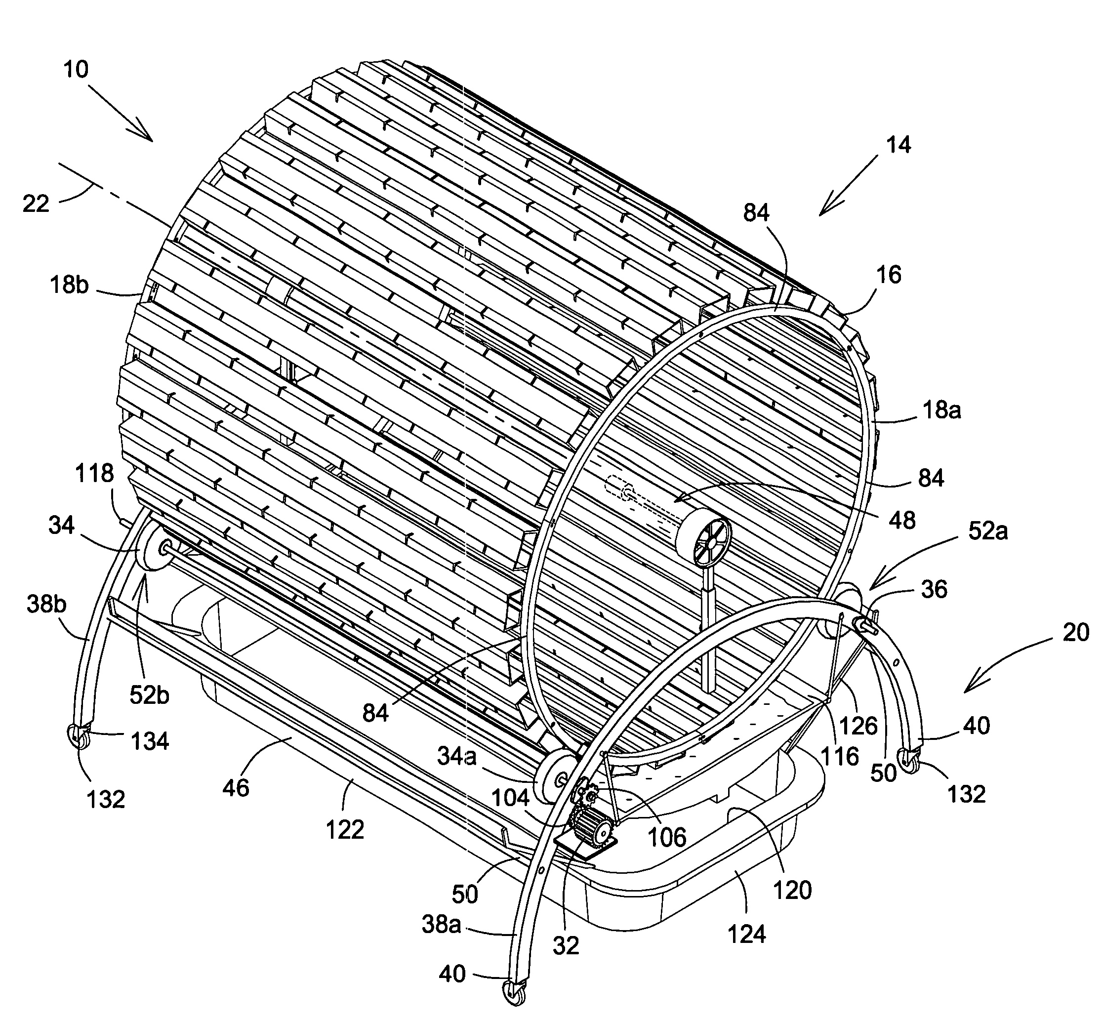
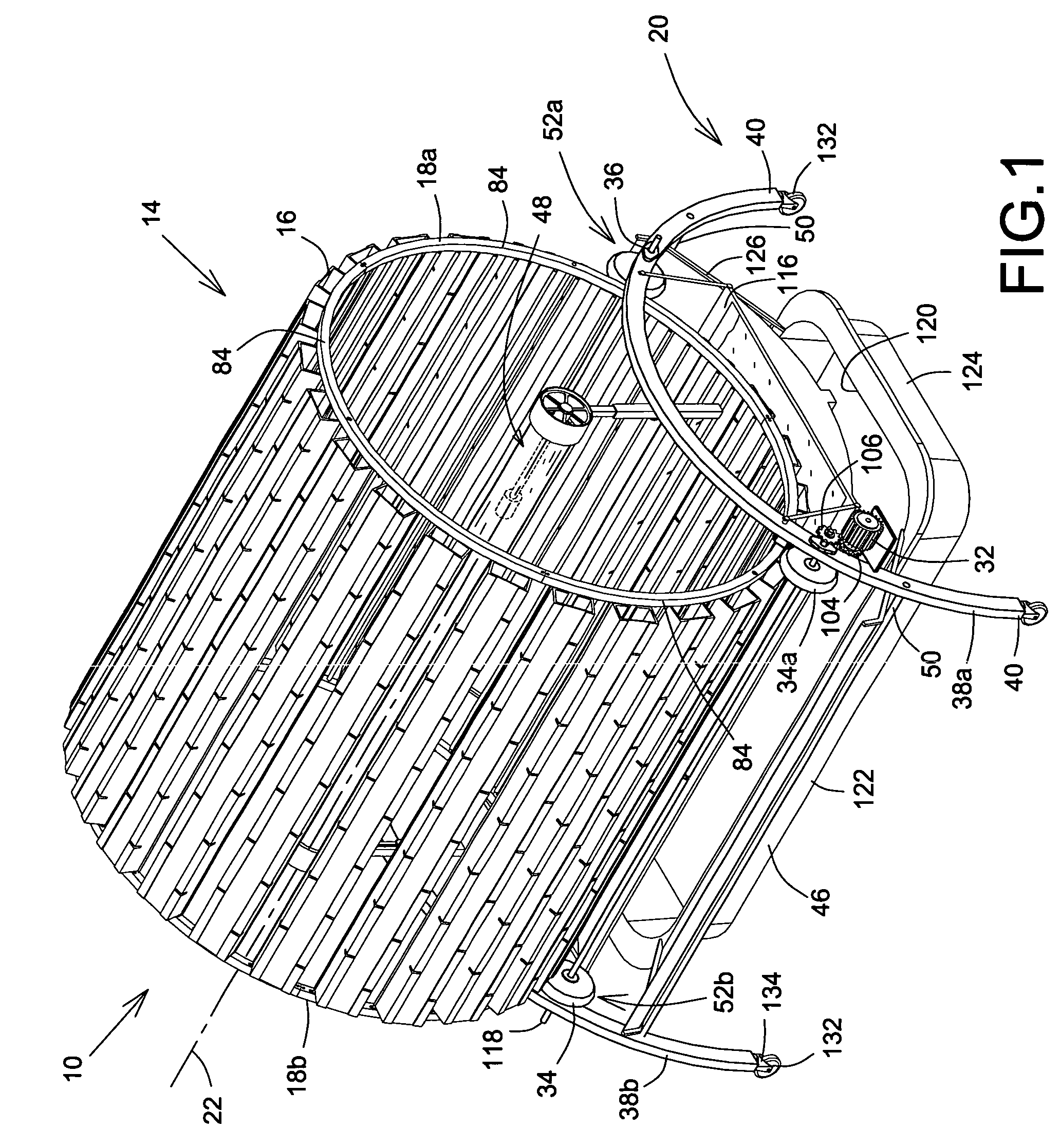
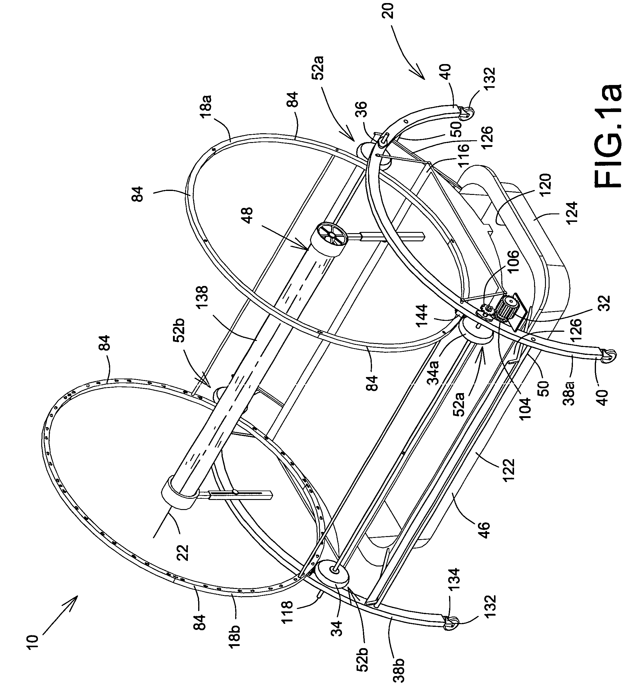
[0024]Referring now to FIGS. 1, 1a, and 2, there is shown an embodiment of a rotary plant growing apparatus, shown generally as 10, for growing plants 12. Generally speaking, the apparatus 10 has a support base, shown generally as 20, and a cylindrical structure, shown generally as 14, having generally circular first and second rims 18a, 18b and at least one basket 16 extending therebetween and attached thereto, rotatably mounted on the support base 20 for rotation about a rotational axis 22. The basket 16 contains a growing medium 24, such as earth, peat moss, or any other medium capable of supporting and sustaining the growth of at least one plant planted or otherwise placed in the growing medium 24 in the basket 16. In order to provide nutrients, such as water and fertilizer, for growth of the plant 12, th...


PUM


Abstract

A rotary plant growing apparatus has a cylindrical structure rotatably mounted on a support base. The cylindrical structure consists of a plurality of baskets in which plants may be grown and rotates around a rotational axis such that the baskets are at least partially immersed in nutrient reservoir containing a liquid nutrient for nourishing the plants. A light source extending at least partially through the cylindrical structure provides light for growth of plants. The baskets are securely and removably attached to rims of the cylindrical structures by pins extending therefrom and which have heads which retaining the pins in apertures therefore on the rims. A motor and gear arrangement provides rotation of the cylindrical structure.

Description

FIELD OF THE INVENTION[0001]The present invention relates to plant growing apparatuses and is more particularly concerned with a rotary plant growing apparatus.BACKGROUND OF THE INVENTION[0002]It is well known in the art to use to use a rotary plant growing apparatus to grow plants in either indoor or outdoor environments. For example, U.S. Pat. No. 6,840,007, issued to Leduc et al. on Jan. 11, 2005, teaches such an apparatus in which a cylindrical structure, comprising a plurality of baskets connected to two generally opposed circular rims in a circumferentially spaced apart configuration, mounted on a support base and which is rotated on the support base about a rotational axis by a wheel in abutting contact therewith and which is rotated by a motor connected thereto by chains, sprockets, and the like. The baskets contain a growing medium which supports growth of the plants and which allows absorption of a liquid nutrient for feeding the plants during growth. The liquid nutrient i...

Claims


Application Information

Patent Timeline
Patent Type & Authority Patents(United States)
IPC IPC(8): A01G31/02A01G31/06
CPCA01G9/00A01G25/00A01G9/02A01G31/047Y02P60/21
Inventor SOUVLOS, ANGELOSACARETSANOS, COSTAZOUBOULAKIS, TERRY
Owner SOUVLOS ANGELO
Learn More