
Check valve for chemical fiber spinning device

A shut-off valve and equipment technology, applied in mechanical equipment, lifting valves, valve details, etc., can solve the problems of easy retreat, melt leakage, high cost, etc., and achieve the effect of self-locking

Inactive Publication Date: 2016-01-06
SUZHOU JWELL POLY ENG
View PDF10 Cites 3 Cited by
  • Summary
  • Abstract
  • Description
  • Claims
  • Application Information

AI Technical Summary

Problems solved by technology

[0003] In the prior art, most adopt non-contact freezing valve device or ordinary type threaded shut-off valve to carry out interception, but each has its own shortcomings: 1. Non-contact freezing The valve device uses compressed air to blow across the surface of the melt pipeline to take away the heat and cool the melt in the pipeline to form a plug to close the melt passage, but it is not suitable for the working condition of large pressure difference and flowing melt , especially for high-viscosity and high-enthalpy melts, the freezing time is as long as ten hours, and the operation waiting time is long, and this method uses a large amount of compressed air and high energy consumption; It cannot be fixed, and it is easy to retreat under the action of pressure, resulting in the loss of the cut-off function, and there is no valve core, and the valve stem directly acts on the valve body. After repeated use, the deformation of the valve body cannot completely close the melt passage, and frequent melt leakage The valve body is a component welded inside the spinning box. When the valve body fails, the entire line needs to be shut down, and the cost of opening the spinning box to replace the shut-off valve is relatively high, and because the insulation medium in the spinning process is biphenyl , prone to chemical poisoning, and there are potential safety hazards of flammability and explosion, and the risk factor is large

Method used


Image

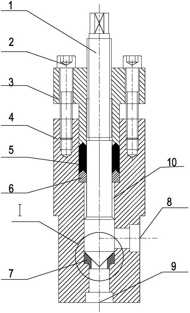
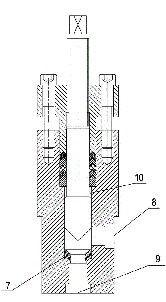
  • Check valve for chemical fiber spinning device
  • Check valve for chemical fiber spinning device
  • Check valve for chemical fiber spinning device

Examples


Embodiment Construction

[0020] The present invention will be described in detail below in conjunction with the embodiments shown in the accompanying drawings. figure 1 The upper and lower positional relationship in .

[0021] See attached Figure 1~4 As shown, this embodiment discloses a shut-off valve for chemical fiber spinning equipment, which is arranged on the melt channel of the chemical fiber spinning equipment. The shut-off valve includes a valve body 4, a valve cover 3, a valve stem 1, fastening screws 2, and a valve core 7. The valve body 4 is provided with a valve cavity that penetrates up and down. The valve cavity includes the second center hole 12, the first center hole 11, the third center hole 13 and the melt outlet 9 arranged in sequence from top to bottom, and the second center The inner diameter of the hole 12 is larger than the inner diameter of the first central hole 11 , and the inner diameter of the first central hole 11 is larger than the inner diameter of the third central ...


PUM


Abstract

The invention discloses a check valve for a chemical fiber spinning device. The check valve comprises a valve body, a valve deck, a valve rod, a fastening screw and a valve element. The lower end of the valve rod and the lower end of the valve deck stretch in a valve cavity. The upper portion of the valve rod is connected with the valve deck in a matched manner through a self-locking thread. The lower end of the fastening screw penetrates the valve deck and is pre-tightened to the valve body. An elastic washer is arranged between the valve deck and the valve body. A melt inlet and a melt outlet are formed in the valve body. The valve element is located in a channel for the melt inlet and the melt outlet to be communicated. The lower end of the valve rod is provided with a first sealing face used for being in sealing fit with the valve element, and a peripheral face in clearance fit with the valve cavity. The valve element is provided with a second sealing face. According to the check valve for the chemical fiber spinning device, when a spinning function element needs to be replaced, flowing of a melt is fast and reliably cut off to achieve cut-off, in the closed state of the check valve, the position of the valve rod cannot be influenced by pressure so that the position cannot change, self-locking can be achieved, and the check valve is particularly suitable for high-viscosity, high-enthalpy and high-pressure melt cut-off occasions

Description

technical field [0001] The invention belongs to the field of spinning equipment, in particular to a stop valve used in chemical fiber spinning equipment. Background technique [0002] The chemical fiber spinning process is the process of cooling the molten fiber-forming polymer through small holes to obtain continuous chemical fibers. However, the current melt spinning process mostly uses a large-scale production line with multiple stations operating at the same time. During the spinning process, component failures or metering pump damage on the production line often occur. If the entire production line is stopped to repair equipment, equipment The use cost is very high, and the fault location is generally used for local operation and maintenance, but the high-temperature and high-pressure melt will also flow to places with low pressure, and will be ejected from the location where the metering pump or components are removed, causing accidents. Therefore, a cut-off device is...

Claims


Application Information

Patent Timeline
IPC IPC(8): F16K1/02F16K1/38F16K27/02F16K35/00
CPCF16K1/02F16K1/385F16K27/0254F16K35/00
Inventor 何海潮吕山王涛
Owner SUZHOU JWELL POLY ENG
Learn More