


Quick Research
Generate reliable direction feasibility study reports for your R&D in just a few steps.

Technical Q&A
Discover and master advanced knowledge NOW. Basics, ideas, possibilities, all at once.

Find Solutions
As an expert in R&D theories, this can generate solutions to your technical problems instantly.

Evaluate Feasibility
Analyze your overall solution with one click, know your potential R&D risks in advance.

Monitor Landscape
Get weekly tech updates, stay abreast of the latest tech innovations and key insights.
Gas turbine combined cycle equipment and water equipment
A gas turbine and combined cycle technology, applied in gas turbine installations, mechanical equipment, combined combustion mitigation, etc., can solve the problems of higher center of gravity of equipment and larger swing of water equipment, and achieve the effect of improving stability
- Summary
- Abstract
- Description
- Claims
- Application Information
AI Technical Summary
Problems solved by technology
Method used
Image

Examples
no. 1 Embodiment approach
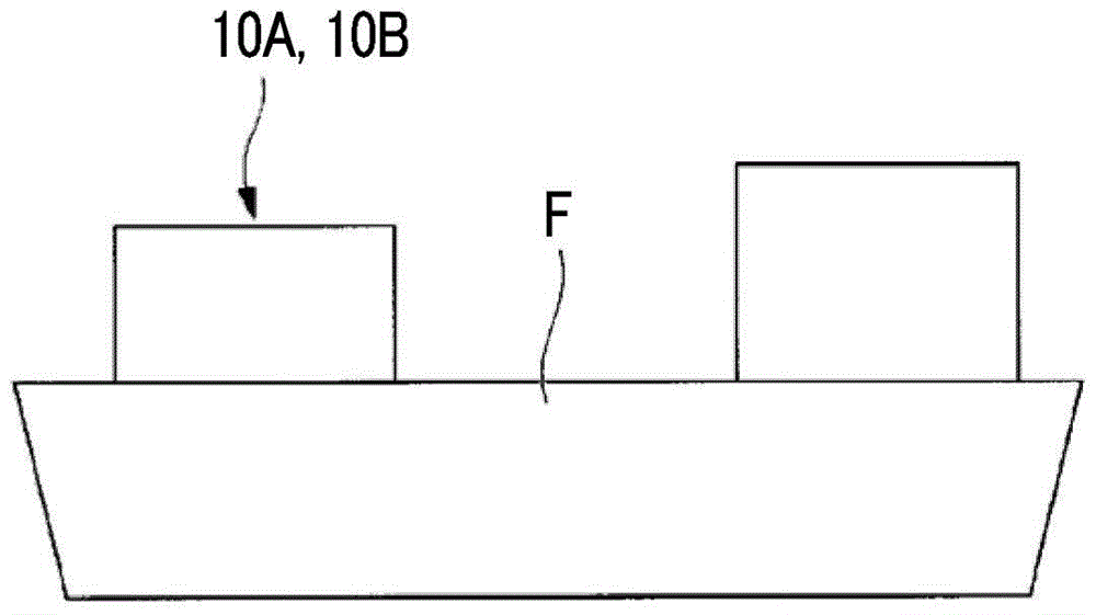
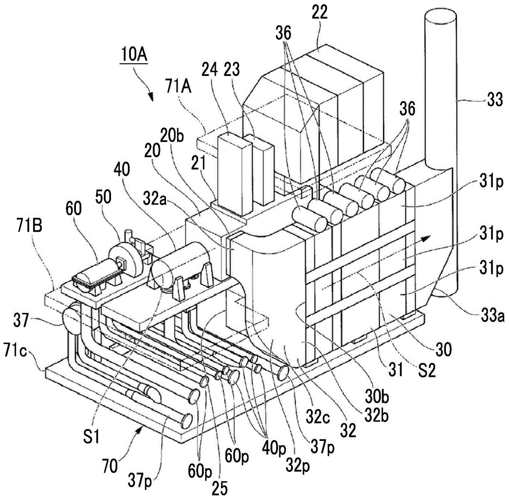
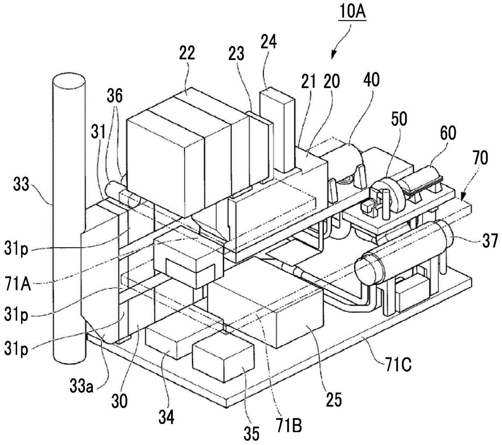
[0034] figure 1 It is a figure which shows the schematic structure of the ship provided with the gas turbine combined cycle facility (it abbreviates to GTCC facility hereafter) which concerns on this embodiment. figure 2 It is a perspective view showing the configuration of the GTCC facility according to this embodiment, image 3 for following with figure 2 A perspective view of the GTCC facility according to the present embodiment viewed from different angles. Figure 4 It is a perspective view showing the structure of a waste heat recovery boiler installed in a GTCC facility.
[0035] Such as figure 1 As shown, the above-water facility in this embodiment liquefies natural gas, for example. This water surface facility includes a ship (floating body) F and 10A of GTCC facilities. Vessel F is used on-site at sea for the extraction of liquefied natural gas. GTCC facility 10A is installed on this ship F.
[0036] Such as figure 2 , image 3 As shown, GTCC facility 10A...
no. 2 Embodiment approach
[0112] Next, a second embodiment of the gas turbine combined cycle facility and marine facility according to the present invention will be described. In the second embodiment described below, the reference figure 1 , and the same reference numerals are assigned to the same configurations as those in the above-mentioned first embodiment, and descriptions thereof will be omitted.
[0113] Figure 6 It is a perspective view showing the configuration of the GTCC facility according to the embodiment according to the second embodiment.
[0114] Such as Figure 6 As shown, the GTCC facility 10B of the present embodiment mainly includes a gas turbine unit 20 , a waste heat recovery boiler 30 , an exhaust connection duct 32 , a compressor 80 , and a support frame 70 . The gas turbine unit 20 is driven by, for example, natural gas as fuel. The waste heat recovery boiler 30 generates steam by recovering waste heat of exhaust gas from the gas turbine unit 20 . The compressor 80 is us...
PUM
 Abstract
Description
Claims
Application Information
 - R&D Engineer
- R&D Manager
- IP Professional
- Industry Leading Data Capabilities
- Powerful AI technology
- Patent DNA Extraction
Browse by: Latest US Patents, China's latest patents, Technical Efficacy Thesaurus, Application Domain, Technology Topic, Popular Technical Reports.
© 2024 PatSnap. All rights reserved.Legal|Privacy policy|Modern Slavery Act Transparency Statement|Sitemap|About US| Contact US: help@patsnap.com