
Non-intrusive mode electrical load identification system and method

An electricity load, non-intrusive technology, applied in information technology support systems, electrical components, circuit devices, etc., can solve problems such as high hardware performance requirements, potential safety hazards, shadows, etc.

Inactive Publication Date: 2015-12-23
ELECTRIC POWER RESEARCH INSTITUTE, CHINA SOUTHERN POWER GRID CO LTD
View PDF3 Cites 105 Cited by
  • Summary
  • Abstract
  • Description
  • Claims
  • Application Information

AI Technical Summary

Problems solved by technology

[0002] Electric load monitoring and identification has always been a key technology in the field of intelligent electricity consumption. Traditional electricity load monitoring equipment needs to install data acquisition modules, microprocessors, sensors, communication modules and other monitoring terminals on the power supply side of user electrical equipment. Monitoring terminals Communication with the main station through the indoor wireless LAN, this intrusive load monitoring system needs to install a load monitoring terminal independently for each electrical equipment, the construction cost is high, the operation and maintenance are difficult, and it may affect the production and life of users at the same time; In addition, the load monitoring terminal and the monitoring master station use wireless local area network for data communication, and there are hidden dangers in the user's power consumption information, which does not conform to the development trend of two-way interactive intelligent power consumption technology; For high-frequency data collection and analysis, the time overhead and space overhead of the algorithm are large, and the hardware performance requirements are high, so it is impossible to realize remote online load identification of multiple electrical equipment at the same time

Method used


Image

  • Non-intrusive mode electrical load identification system and method
  • Non-intrusive mode electrical load identification system and method
  • Non-intrusive mode electrical load identification system and method

Examples


Embodiment Construction

[0062] The present invention is further described below in conjunction with accompanying drawing and embodiment:

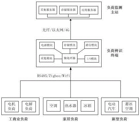
[0063] Such as figure 1 As shown, a non-intrusive electric load identification system includes electric load, load identification terminal, and load monitoring master station; the electric load communicates with the load identification terminal through RS485, Zigbee, and Wifi communication protocols, and the load identification The terminal performs information exchange with the main load monitoring station through optical fiber, Ethernet, and wireless public network; the load identification terminal uploads the identification results of the power load to the main load monitoring station, and the main station of the load monitoring monitors the type of power load and its usage Online statistical analysis of electrical characteristics.

[0064] The load identification terminal consists of an acquisition module, a storage module, a communication module, an input / ou...


PUM


Abstract

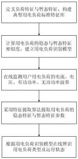
The invention discloses a non-intrusive mode electrical load identification system and method. The load identification system comprises electrical load, a load identification terminal and a load monitoring main station; and the load identification terminal performs information interaction with the load monitoring main station through modes of optical fibers, an Ethernet and a wireless public network. The load identification terminal, by analyzing waveform characteristics of current, voltage, active power and the like of typical electrical equipment, defines different characteristic parameters based on a steady state process and a transient state process to establish a standard transient library, and then establishes an electrical load identification model by combination of the steady state and the transient state characteristic similarity of the electrical equipment. The identification system module is high in integration level, the terminal is smaller in size, the construction cost of the system is lower, the running and maintaining of the system are simple without affecting production and life of users; and the non-intrusive mode electrical load identification method can realize accurate identification of load types and running states of multiple paths of electrical equipment at the same time.

Description

technical field [0001] The invention relates to a non-invasive electric load identification system and method. Background technique [0002] Electric load monitoring and identification has always been a key technology in the field of intelligent electricity consumption. Traditional electricity load monitoring equipment needs to install data acquisition modules, microprocessors, sensors, communication modules and other monitoring terminals on the power supply side of user electrical equipment. Monitoring terminals Communication with the main station through the indoor wireless LAN, this intrusive load monitoring system needs to install a load monitoring terminal independently for each electrical equipment, the construction cost is high, the operation and maintenance are difficult, and it may affect the production and life of users at the same time; In addition, the load monitoring terminal and the monitoring master station use wireless local area network for data communicatio...

Claims


Application Information

Patent Timeline
IPC IPC(8): H02J13/00G06F17/50
CPCY04S40/124Y04S40/126Y02E60/00
Inventor 赵云李秋硕孙宇军肖勇
Owner ELECTRIC POWER RESEARCH INSTITUTE, CHINA SOUTHERN POWER GRID CO LTD
Learn More