
Electronic tube plate electrode blocking capacitor

A technology for capacitors and electronic tubes, applied in the field of capacitors, can solve the problems of complex manufacturing of PTFE cylinders, poor contact of reeds, and increased costs, etc., and achieve the effect of simple appearance, normal use, and weight reduction

Inactive Publication Date: 2015-12-23
周晓
View PDF0 Cites 8 Cited by
  • Summary
  • Abstract
  • Description
  • Claims
  • Application Information

AI Technical Summary

Problems solved by technology

[0005] 2. In order to ensure the withstand voltage requirements of the capacitor, the two ends of the polytetrafluoro cylinder are set as arc-shaped outward flanging, which will cause the complexity of the processing and manufacturing of the polytetrafluoro cylinder and increase the cost
[0006] 3. Copper cooling air duct is heavy and expensive
[0007] 4. The electrical connection between piece 1 and the electronic tube is connected by the connecting ring of the piece. The connecting ring is composed of the ring body and the reeds located inside and outside the ring. The inner wall is in contact with electricity, and under the condition of high current, the reed often has poor contact, heat, or even burns out.

Method used


Image

  • Electronic tube plate electrode blocking capacitor
  • Electronic tube plate electrode blocking capacitor
  • Electronic tube plate electrode blocking capacitor

Examples


Embodiment Construction

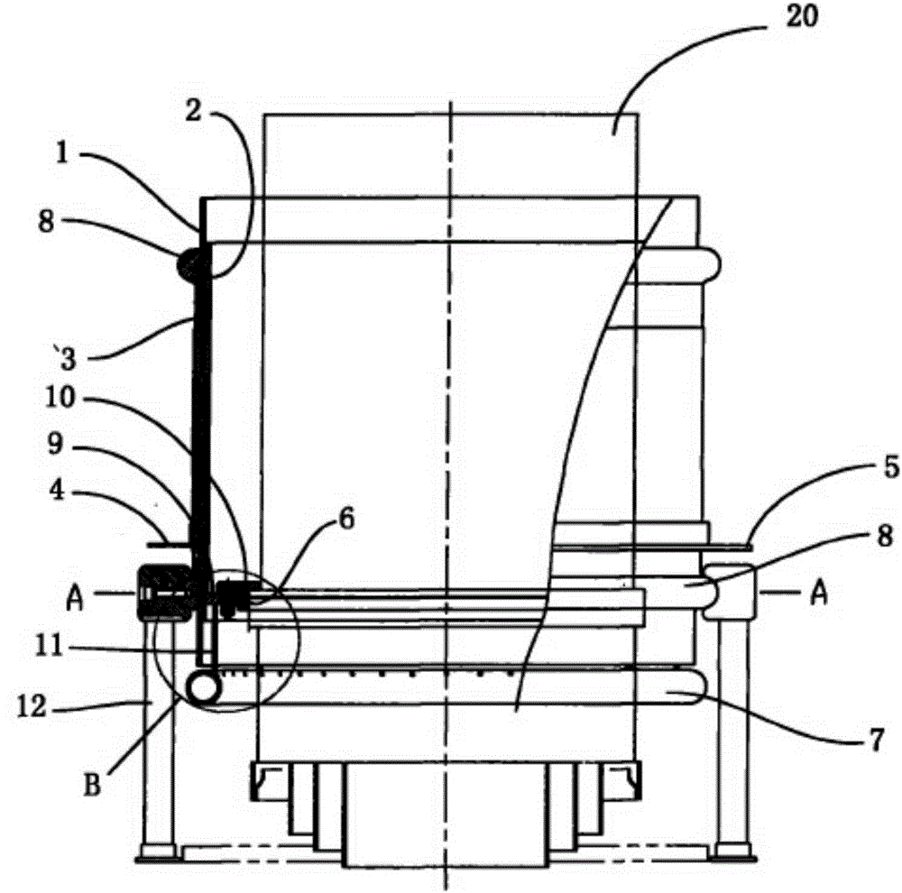
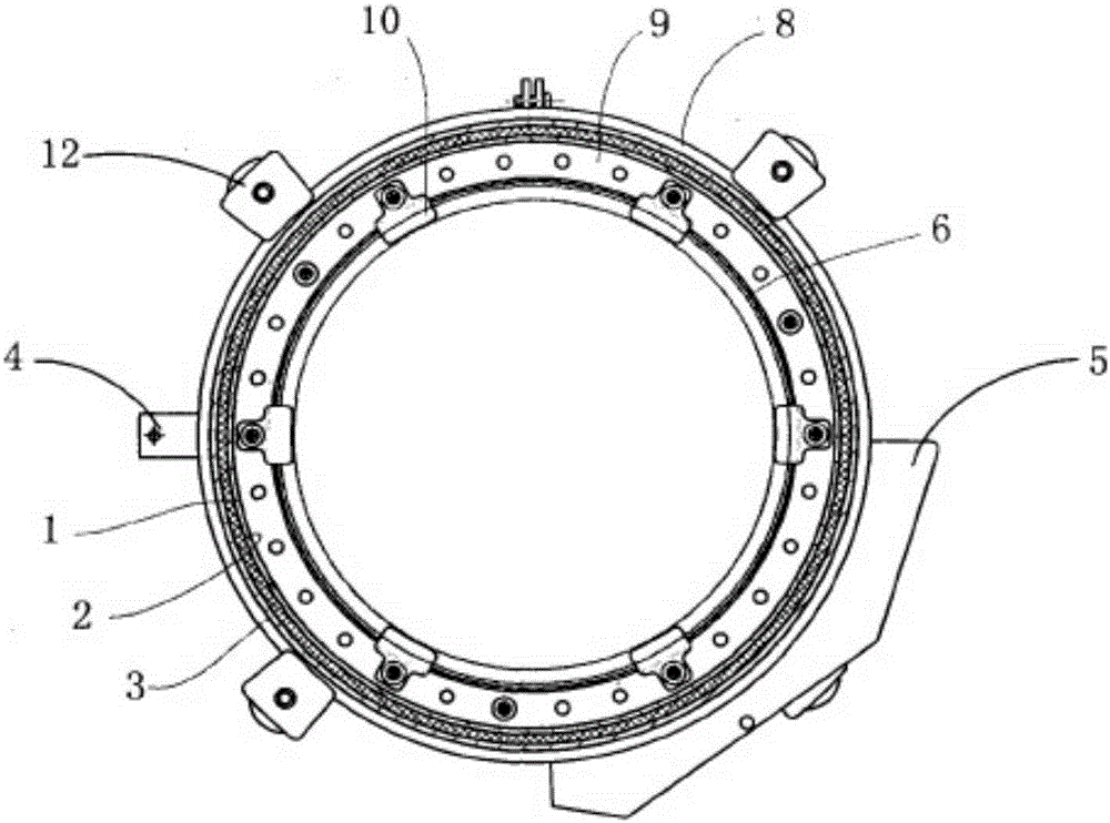
[0033] see figure 2 , image 3 As shown, a kind of electronic tube plate pole DC-blocking capacitor provided by the present invention comprises: polytetrafluoro cylinder 1, inner and outer pole plates 2, 3 which are arranged on the inner and outer surfaces of said polytetrafluoro cylinder 1, welded on the said polytetrafluoro cylinder 1 Describe the connecting angle 4 and connecting plate 5 on the outer surface pole plate 2, the annular contact reed 6 arranged on the inner pole plate electrically connected with the electron tube plate and the cooling air pipe 7 arranged under the polytetrafluoro cylinder, Wherein the inner pole plate 2 is a thin-walled metal inner cylinder, and the thin-walled metal inner cylinder as the inner pole plate is combined with the polytetrafluoro cylinder 1 by interference fit; the outer pole plate 3 is a thin-walled metal inner cylinder. The outer cylinder, the thin-walled metal outer cylinder as the outer pole plate 3 is interference-bonded with...


PUM


Abstract

The invention relates to a capacitor and particularly relates to an electronic tube plate electrode blocking capacitor which is used for an electronic tube plate electrode of high-frequency high-power transmission equipment. The electronic tube plate electrode blocking capacitor comprises a polytetrafluoroethylene barrel, inner and outer polar plates arranged on the inner and outer surfaces of the polytetrafluoroethylene barrel, a connection corner and a connection plate which are welded on the polar plate on the outer surface, an annular contact reed which is electrically connected with the electronic tube plate electrode and is arranged on the inner polar plate, and a cooling air pipe arranged under the polytetrafluoroethylene barrel, wherein the inner polar plate is a thin-wall metal inner barrel, and the thin-wall metal inner barrel used as the inner polar plate is combined with the polytetrafluoroethylene barrel through interference fit; the outer polar plate is a thin-wall metal outer barrel; and the thin-wall metal outer barrel used as the outer polar plate is combined with the polytetrafluoroethylene barrel through interference fit, and circular-arc-shaped corona rings are arranged at the two ends of the thin-wall metal outer barrel used as the outer polar plate. With the adoption of the electronic tube plate electrode blocking capacitor, the problem that the connection corner and a connection plate lamp are welded on the polar plates so that the insulation performance of part of the polytetrafluoroethylene barrel is reduced is solved.

Description

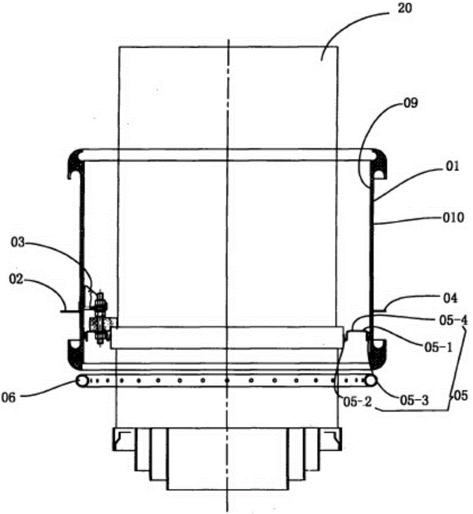
technical field [0001] The invention relates to a capacitor, in particular to an electron tube plate DC blocking capacitor (hereinafter referred to as a DC blocking capacitor) used for the electron tube plate of high-frequency and high-power transmission equipment. Background technique [0002] DC blocking capacitor is the core component of high-frequency and high-power (electron tube) transmission equipment, and occupies an important position in transmission equipment. The existing DC blocking capacitor used for 500kW shortwave transmitter is a cylindrical capacitor, and its structure is as follows figure 1 As shown, it includes: polytetrafluoro cylinder 01, the inner and outer surfaces of the polytetrafluoro cylinder 01 are coated with metal silver-plated layers 09 and 010 as the inner and outer plates of the capacitor, and the metal silver-plated layer 010 of the outer plate is A connecting angle 02 and a connecting plate 04 are welded, and a supporting angle 03 is welde...

Claims


Application Information

Patent Timeline
IPC IPC(8): H01G4/005H01G2/08H01G4/018
Inventor 周晓
Owner 周晓
Learn More