Heavy oil processing coking prevention method and fractionating tower

A fractionation tower, anti-coking technology, applied in the petroleum industry, hydrocarbon distillation, etc., can solve the problems of long residence time, overheating of circulating oil slurry, affecting production, etc., and achieve the effect of shortening residence time and avoiding local overheating

Inactive Publication Date: 2015-12-23
刘英聚
View PDF0 Cites 6 Cited by
  • Summary
  • Abstract
  • Description
  • Claims
  • Application Information

AI Technical Summary

Problems solved by technology

At present, the industrial catalytic cracking unit is equipped with a cold oil slurry loop and a stirring steam loop at the bottom of the fractionation tower, and enters part of the low-temperature (250-280°C) circulating oil slurry to cool down the bottom oil slurry, and introduces steam to stir, or often Coking occurs in the fractionation tower system of heavy oil catalytic cracking unit or coking unit and affects production
Analysis of the current status of fractionation towers in industrial installations requires improvement in the following three aspects: 1. The residence time of high-temperature oil and gas at 500°C in the tower is relatively long; ℃ high-temperature oil and gas reverse contact, uneven flow of oil slurry will cause local overheating of circulating oil slurry; 3, 360-365 ℃ high-temperature circulating oil slurry does not cool down in time and stays in the tower for a relatively long time

Method used


Image

  • Heavy oil processing coking prevention method and fractionating tower
  • Heavy oil processing coking prevention method and fractionating tower

Examples


Embodiment Construction

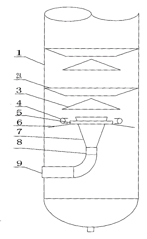
[0015] See figure 1 , is that the washing and desuperheating section 1 of the fractionating tower adopts the cone ring baffle plan, and the liquid guiding skirt 6 is arranged under the washing and superheating section 1 of the fractionating tower. There is a gap between the outer edge of the plate 6 and the wall of the fractionation tower 1, and the rapid cooling medium distribution pipe 4 is arranged above the liquid collecting skirt 6. An oil and gas guide pipe 8 is arranged under the washing and desuperheating section 1 of the fractionating tower, the lower end of which is connected to the oil and gas inlet 9, and the upper end is connected to the lower mouth of the bell mouth 7, and the upper mouth of the bell mouth 7 passes through the central air hole 5 and extends to the liquid collecting skirt plate 6 above.

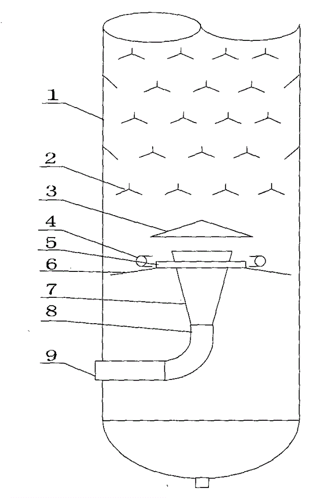
[0016] See figure 2 , is that the washing and desuperheating section 1 of the fractionating tower adopts the herringbone baffle scheme, and the liquid guiding...


PUM


Abstract

A heavy oil processing coking prevention method belongs to the technical field of petroleum chemical engineering and process apparatuses, and is used to solve the coking problem of heavy processing fractionating towers. The method comprises the steps of fractionating tower washing desuperheating, high temperature oil gas entrance, low temperature cycle slurry oil entrance, low temperature oil gas discharge and high temperature cycle slurry oil discharge. The method is characterized in that a high temperature oil gas guiding device is arranged to guide high temperature oil gas entering the tower to a fractionating tower washing desuperheating segment, so the retention time of the high temperature oil gas in the fractioning tower is shortened, direct contact of high temperature cycle slurry oil with the high temperature oil gas is avoided, and local superheating of the high temperature cycle slurry oil is avoided; and the lower end of the washing desuperheating segment is provided with a high temperature cycle slurry oil collecting liquid guiding and cooling device in order to timely and rapidly reduce the temperature of the cycle slurry oil, so the retention time of the high temperature cycle slurry oil is shortened. The invention also provides an oil gas guiding tube, a liquid collecting and guiding skirt board and a rapid cooling medium distribution tube fractioning tower for realizing the method. The method maximally shortens the retention time of the high temperature oil gas and the high temperature cycle slurry oil and avoids local superheating of the cycle slurry oil in order to avoid system coking of the fractioning tower, and is applied in heavy oil catalytic cracking and coking fractionate towers.

Description

technical field [0001] The invention belongs to the technical field of petrochemical industry and process equipment, and in particular relates to an anti-coking method for heavy oil processing and a fractionation tower. Background technique [0002] The lower part of the fractionation tower of the heavy oil catalytic cracking unit or coking unit is equipped with a washing and superheating section, which uses 250-280°C circulating oil slurry to wash and remove the catalyst powder carried by high-temperature oil and gas, and reduce the temperature of the oil and gas from 500°C to 360-365°C to remove High-temperature oil and gas superheat; 250-280 °C circulating oil slurry completes the washing and de-superheating task, the temperature rises to 360-365 °C, and then falls into the bottom of the fractionation tower. The content of polycyclic aromatic hydrocarbons in the circulating oil slurry is as high as 80%. Under the conditions of high temperature above 360°C and long residen...

Claims


Application Information

Patent Timeline
IPC IPC(8): C10G7/00
Inventor 刘英聚
Owner 刘英聚
Why Eureka
Try Eureka