
Urea hydrolysis reactor control system and urea hydrolysis reactor control method based on heat feed-forward signals

A hydrolysis reactor and feed-forward signal technology, which is applied to controllers with specific characteristics, electric controllers, etc., can solve problems such as slow changes in the working temperature of hydrolysis reactors, slow response speed to variable load commands, and frequent steam valve actions. , to achieve the effect of stable and reliable control signal, reduced amplitude and easy realization

Active Publication Date: 2015-12-02
CHINA HUANENG GRP CO LTD +1
View PDF11 Cites 4 Cited by
  • Summary
  • Abstract
  • Description
  • Claims
  • Application Information

AI Technical Summary

Problems solved by technology

Due to the large size of the hydrolysis reactor and a large amount of high-temperature urea solution stored in the container, the working temperature of the hydrolysis reactor changes slowly under the action of thermal inertia, coupled with the heat conduction process of the heating steam, from the gas phase outlet valve action to the heating steam valve action The elapsed time will be very long, the response speed of the hydrolysis reactor to the load changing command is very slow, the steam valve moves frequently during the load changing process, and the heat waste is very serious
On the other hand, the shutdown process of the urea hydrolysis plant is relatively slow. When the ammonia gas supply needs to be cut off quickly due to a fault in the SCR area, how to control the emergency shutdown of the urea hydrolysis plant is also an urgent problem to be solved.

Method used


Image

  • Urea hydrolysis reactor control system and urea hydrolysis reactor control method based on heat feed-forward signals
  • Urea hydrolysis reactor control system and urea hydrolysis reactor control method based on heat feed-forward signals
  • Urea hydrolysis reactor control system and urea hydrolysis reactor control method based on heat feed-forward signals

Examples


Embodiment Construction

[0025] The present invention will be further described in detail below in conjunction with specific embodiments, which are explanations of the present invention rather than limitations.

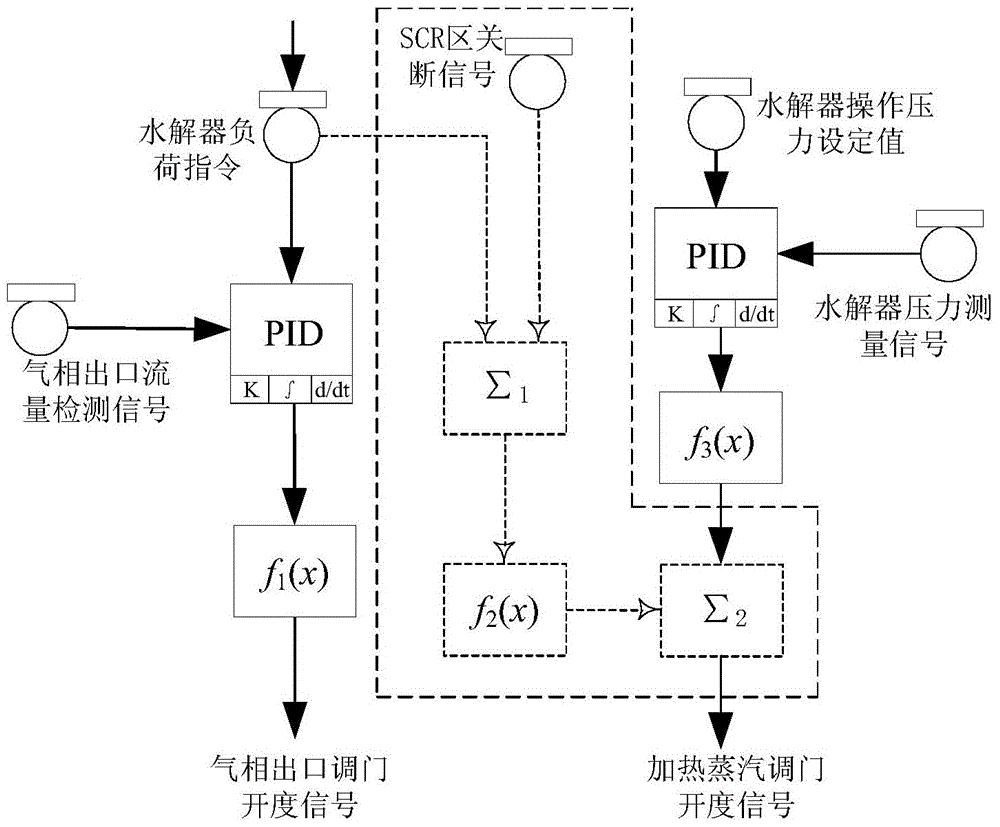
[0026] The present invention is based on the urea hydrolysis reactor control method of heat feed-forward signal, such as figure 1 As shown, it includes the following steps,

[0027] 1) The transfer function f from the load of the hydrolysis reactor to the amount of heating steam is obtained by fitting the operating data of the urea hydrolysis reactor 2 (x);

[0028] 2) From the hydrolysis reactor load command through the transfer function f 2 (x) generating a heating steam consumption signal, and converting it into a corresponding first heating steam regulating door opening signal according to the linear relationship between the heating steam consumption signal and the heating steam regulating door opening signal;

[0029] 3) According to the set value and measured value of the pressure of...


PUM


Abstract

The invention relates to a urea hydrolysis reactor control method based on the heat feed-forward signals, which comprises the steps of 1) acquiring a transfer function from a hydrolysis rector load to heating steam consumption; 2) generating a path of heating steam consumption signals through the transfer function by a hydrolysis rector load instruction, and converting the heating steam consumption signals into corresponding first heating steam governing valve openness signals; 3) generating second heating steam governing valve openness signals through a governing valve openness control function by a hydrolysis rector pressure deviation signals, and acquiring a deviation value; 4) leading the first heating steam governing valve openness signals into heating steam governing valve openness automatic control logic to act as feed-forward signals, and determining an openness reference value; and 5) weighing the heating steam governing valve openness reference value and the deviation value, outputting the weighed heating steam governing valve openness reference value and the weighed deviation value so as to acquire heating steam governing valve openness signals under variable load conditions. The control system provided by the invention comprises a PLC (programmable logic controller) which is used for receiving the hydrolysis reactor load instruction, a hydrolysis reactor pressure set value and measurement signals.

Description

technical field [0001] The invention relates to a technology for producing ammonia by urea hydrolysis for denitrification in a thermal power plant, in particular to a control system and method for a urea hydrolysis reactor based on a heat feedforward signal. Background technique [0002] In recent years, domestic and foreign power generation companies have paid more and more attention to the potential dangers in the use of liquid ammonia. In some special areas and coal-fired power plants that are close to cities and residential areas, urea hydrolysis to ammonia has become an important method for the preparation of SCR denitrification and reduction. The recommended process for the agent. [0003] The urea hydrolysis ammonia production process has been gradually applied in the SCR denitrification reducing agent preparation section of thermal power plants. Ammonia production system; CN202430017U, a urea hydrolyzer applied to flue gas denitrification; CN201458752U; urea hydroly...

Claims


Application Information

Patent Timeline
Patent Type & Authority Applications(China)
IPC IPC(8): G05B11/42
Inventor 张向宇张波李明皓向小凤高宁徐宏杰
Owner CHINA HUANENG GRP CO LTD
Learn More