
Screw compressor possessing oil separator and water chilling unit

一种螺杆压缩机、油分离器的技术,应用在压缩机、压缩机、不可逆循环的压缩机器等方向,能够解决油分离效果不佳、油分离效率低、零件数目众多等问题,达到提高安全性和可靠性能、高分油效率、降低制造和安装成本的效果

Active Publication Date: 2015-11-25
CARRIER CORP
View PDF10 Cites 7 Cited by
  • Summary
  • Abstract
  • Description
  • Claims
  • Application Information

AI Technical Summary

Problems solved by technology

[0008]However, the above-mentioned screw compressor not only has a complex structure, a large number of parts, but also has low oil separation efficiency, and can only meet the requirements of low oil content. system, and for flooded systems with higher oil content requirements, the oil separation effect of screw compressors in the prior art is generally poor, so it is difficult to achieve the optimum separation and recycling of the refrigerated oil inside the screw compressor optimization

Method used


Image

  • Screw compressor possessing oil separator and water chilling unit
  • Screw compressor possessing oil separator and water chilling unit

Examples


Embodiment Construction

[0030] First of all, it should be noted that the orientation terms such as up, down, front, back, left, right, horizontal and vertical mentioned in this article are relative to the screw compressor with oil separator shown in each drawing. Or its components are defined, they are relative concepts, so they may change accordingly according to their different positions and different usage states. Accordingly, these or other directional terms should not be construed as limiting terms.

[0031] Secondly, it should also be pointed out that for any single technical feature described or implied in the embodiments mentioned herein, or any single technical feature shown or implied in the drawings, these technical features (or their equivalents) can still continue to be combined, so as to obtain more other embodiments of the present invention that may not be directly mentioned herein.

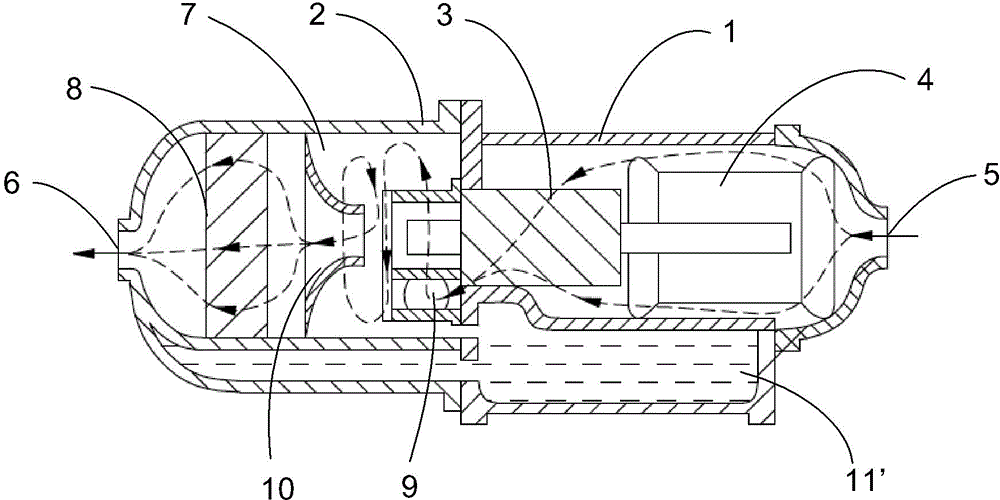
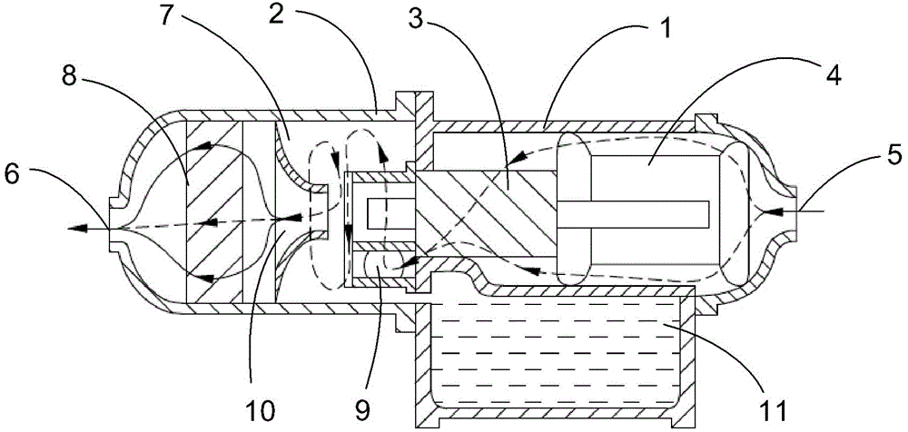
[0032] Please refer to figure 2 , which schematically shows the basic structure of an embodiment of...


PUM


Abstract

The present invention relates to a screw compressor having an oil separator, comprising: a compressor housing with an inlet for a refrigerant gas flow to flow in; an oil separator housing connected to the compressor housing in a fastened and sealed manner and having an outlet for the refrigerant gas flow to flow out; a compressing assembly disposed within the compressor housing and close to the inlet for compressing the refrigerant gas flow; an electric motor for driving the compressing assembly; and an oil supply device for supplying a freezing oil to the compressing assembly; the screw compressor further comprises an oil separator, the oil separator is disposed within the oil separator housing and comprises a first separator and a second separator, wherein the second separator is disposed close to the outlet, and the first separator is disposed between the compressing assembly and the second separator.

Description

technical field [0001] The invention relates to a screw compressor with an oil separator, and also relates to a chiller equipped with the screw compressor. Background technique [0002] The Chinese patent application CN202792748 disclosed by Dong Ling proposes a casing cyclone oil separator. The casing cyclone oil separator disclosed in this patent for screw compression heat pumps includes an oil storage cylinder and a porous plate, and is characterized in that it also includes a separation cylinder and a casing cyclone oil separator, and the separation cylinder is located in the oil storage cylinder. In the upper part, one end of the oil storage cylinder is equipped with a porous plate inside, and several groups of identical casing cyclone oil separators are installed in the separation cylinder. The inner and outer tubes are installed coaxially and vertically, the inner tube is short and is a central passage, the outer tube and the inner tube form an annular space, the to...

Claims


Application Information

Patent Timeline
Patent Type & Authority Applications(China)
IPC IPC(8): F04C29/02F04C23/02
CPCF04C18/16F04C29/026F04C23/008F04C29/0085F04C29/0092F04C29/04F04C29/12F04C2240/30F04C2240/40F04C2240/809F25B1/047F25B31/002F25B2400/23
Inventor 葛少飞
Owner CARRIER CORP
Learn More