
A clamping method of a micro-sample clamping device

A clamping device and micro-sample technology, used in workpiece clamping device, preparation of test samples, manufacturing tools, etc., can solve the problems of large linear expansion coefficient, insufficient machining accuracy, and small tightening force.

Active Publication Date: 2017-03-29
EAST CHINA UNIV OF SCI & TECH
View PDF8 Cites 0 Cited by
  • Summary
  • Abstract
  • Description
  • Claims
  • Application Information

AI Technical Summary

Problems solved by technology

Compared with the general manual saw blade or grinding wheel cutting, the wire cutting method has the advantage that not only the cutting surface is relatively flat and smooth, but also the cutting affected layer is very thin in general materials and cutting environments, only about 0.01-0.02mm, and this The defect of the processing method is that it can only process samples with a small diameter and a large thickness. For example, when preparing a 0.5mm thick sample in the small punch test, the bar must be cut into 0.6mm thin slices first. For some stainless steel materials, there are problems of poor thermal conductivity and large linear expansion coefficient. Therefore, grinding with a grinding machine is prone to deformation, so it can only be manually ground with water sand until the required thickness. This not only greatly increases labor intensity but also reduces processing accuracy. less than guaranteed
[0006] In the past, the traditional small sample clamping device often used micro-movement connection, such as slotting on the side of the tooling and fastening with bolts. This method requires high bolt fastening force, and small fastening force leads to unstable clamping. Excessive fastening force will cause bending deformation of the sample after thinning

Method used


Image

  • A clamping method of a micro-sample clamping device
  • A clamping method of a micro-sample clamping device
  • A clamping method of a micro-sample clamping device

Examples


Embodiment Construction

[0054] The present invention will be further described below in conjunction with the accompanying drawings. Those skilled in the art should understand that the embodiments are only for illustration and do not constitute any limitation to the present invention.

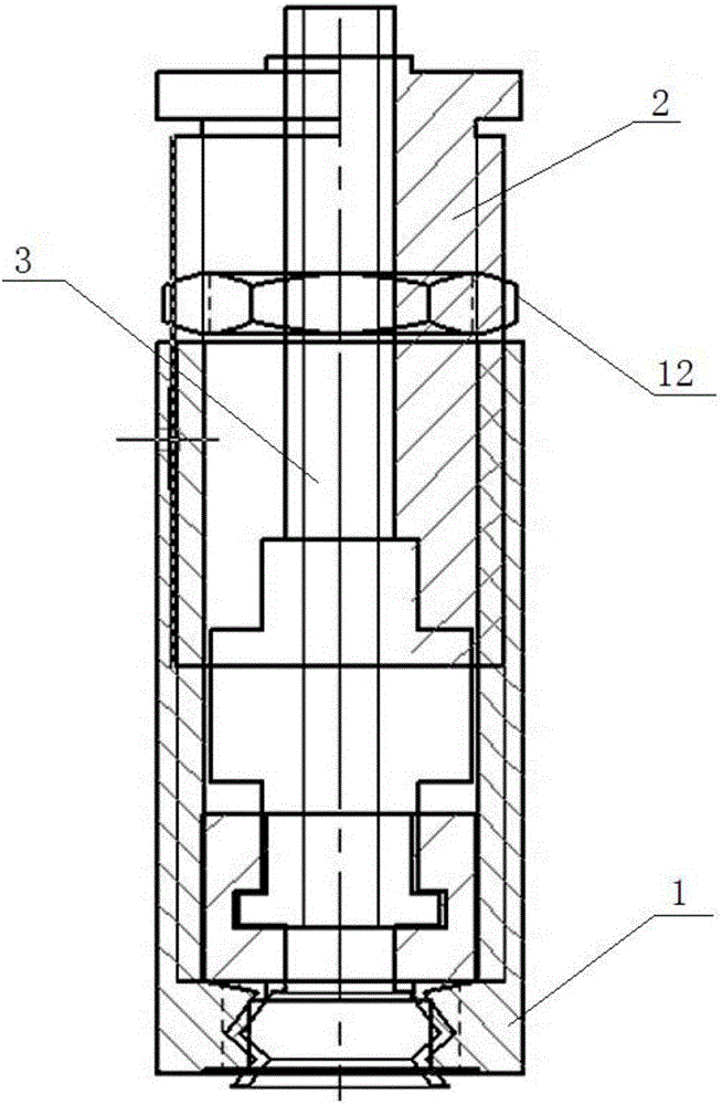
[0055] This embodiment specifically relates to a micro-sample clamping device. The micro-sample clamping device includes an adsorption part, a clamping part, and an adjustment part. After the three parts are assembled, they are connected to a vacuum pump to clamp the micro-sample in the Processing on a grinding machine.

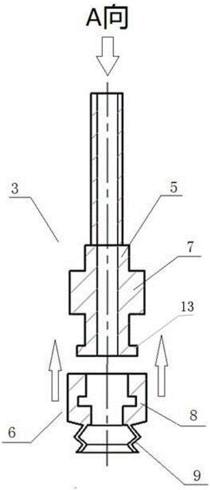
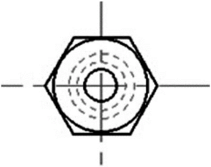
[0056] The adsorption part is composed of a hollow core rod 5, a silica gel suction cup 6 and an air nozzle joint (not shown in the figure). platform 7, and an outer flange 13 is arranged on the bottom edge of its rod body; the silica gel suction cup 6 is specifically composed of a silica gel sleeve 8 and a double-layer suction cup 9, both of which are of an integrated silica gel structure. There is ...


PUM

PropertyMeasurementUnit
thicknessaaaaaaaaaa
diameteraaaaaaaaaa
depthaaaaaaaaaa

Abstract

The invention provides a miniature specimen clamping device and method. The clamping device comprises a clamping component, an adjusting component, a suction component and a vacuum pump. The clamping component is an internally threaded sleeve, wherein the upper portion of the internally threaded sleeve is open, and a hole is formed in the lower portion of the internally threaded sleeve. The adjusting component is an externally threaded sleeve, and the middle of the externally threaded sleeve is through. The clamping component and the adjusting component are in threaded connection in a matched mode to form a cavity in an enclosing mode. The adjusting component is internally provided with a step. The suction component comprises a hollow core rod. The bottom of the hollow core rod is sleeved with a suction cup used for sucking a miniature specimen. A boss matched with the step is arranged on the lower portion of the hollow core rod. The suction component penetrates through the cavity and is connected with the vacuum pump through an air pipe. According to the clamping device, fixation and height adjustment of the suction component are achieved through the clamping component and the adjusting component; meanwhile, the double-layer suction cup on the suction component clamps the miniature specimen stably so that the miniature specimen can be machined on a metallographic grinder; operation is easy, efficiency and accuracy are improved, and the specimen cannot deform or be damaged.

Description

technical field [0001] The invention belongs to the field of sample mechanical performance testing, and in particular relates to a clamping method of a micro-sample clamping device for clamping a micro-sample for metallographic grinding. Background technique [0002] There are a large number of in-service pressure vessels and pipelines in thermal power, nuclear power, petrochemical and metallurgical industries. The materials of these pressure vessels and pipelines will be damaged to varying degrees after long-term service in a certain environment (high temperature, corrosion, etc.). To evaluate the safety of equipment and predict the remaining life of equipment, it is necessary to accurately obtain the mechanical properties of its materials. The most effective and accurate method is to cut the damaged samples of the equipment, and then test and evaluate various properties of materials according to conventional methods, but this method has obvious damage and destruction to th...

Claims


Application Information

Patent Timeline
Patent Type & Authority Patents(China)
IPC IPC(8): B25B11/00G01N1/32
Inventor 董樑惠虎汤晓英钟诚杨帆王路逸倪鹏汤俊雄王晓东徐志岳路亚庆
Owner EAST CHINA UNIV OF SCI & TECH
Learn More